Hardware Setup Guides
- Mobile LPR Setup Equipment List (2024)
- Setting Up an Android Tablet
- Setting Up an LPR Camera (Survision Pikopak)
- Setting Up a PL8RDR (OnLogic)
Mobile LPR Setup Equipment List (2024)
This is the list of equipment that needs to be sent to a client in order to set them up with mobile LPR, as of 2024.
- Android tablet; send in factory box; includes:
- Charger
- Mounting equipment for tablet (optional)
- Bluetooth printer (Star Micronics T-300i recommended); includes:
- Charger
- Roll of blank paper
- LPR camera (Survision Picopak); includes:
- Power cable (modified with 5.5 mm x 2.5 mm barrel connector female end)
- PL8RDR (OnLogic HX310 computer); send in factory box; includes:
- Power adapter (AC to DC 12 V; 5.5 mm x 2.5 mm barrel connector male end)
- 2x Wi-Fi antenna
- 2x 4G LTE antenna (T-bar)
- Mounting equipment
- SIM card; insert into PL8RDR
- Car power adapter (car cigarette lighter to DC 12 V; 5.5 mm x 2.5 mm barrel connector male end)
- Cable splitter (5.5 mm x 2.5 mm barrel connectors; 1 female to 2 male ends)
Setting Up an Android Tablet
Follow these steps to set up a new Android tablet for use with OPS-COM.
Update: Google now requires a phone number to create a new account. Because of this, it is no longer possible to create a new account for each client. Instead, tablets will be sent to clients in their factory condition, along with instructions on how to set up the enforcement app.
Part 1: Creating a Google Account
- Go to this page to create an account. Choose "For myself".
- For the first name, you can use the name of the client's company/institution (e.g. "Tomahawk University"). Last name can be left blank.
- For birthday and gender, you can put anything here; January 1 1970 is commonly used.
- Choose "Create your own Gmail address". The format is [client ID].opscom.hh@gmail.com (e.g. oc_toma.opscom.hh@gmail.com).
- Create the password using the password generator in Zoho Vault.
- Use support@ops-com.com as the recovery email.
- Once complete, go to Zoho Vault and search for "Client Google Accounts for Handhelds". Save the account login in the notes section of that entry.
Part 2: Setting Up the Tablet
- Set up the tablet using the Google account created in the previous part.
- Set the device PIN to 4141.
- For convenience, set the screen timeout to the longest time possible.
- Install the OPS-COM enforcement app and add the device to the client's site (reinstall the app after doing this).
- Pair the Bluetooth printer with the device, and select it in System Settings in the enforcement app.
- If the client is using a Survision LPR camera, enter the the camera's IP address in System Settings in the enforcement app (under "PikoPak camera IPs"). It can also help to set "Include NOREAD Results" to "Any".
Setting Up an LPR Camera (Survision Pikopak)
Follow these steps to set up a new Survision Picopak LPR camera for use with OPS-COM.
Part 1: Setting Up Hardware
- Install the Wi-Fi antenna. Out of the box, the camera comes with a cap installed on the antenna port. Unscrew the cap, and replace it with the antenna.
- Adjust the mount bolts. The camera is attached to a magnetic mount using two bolts on each side. Slightly loosen the forward bolts; this will allow the client to adjust the camera vertically.
- Modify the cable. The power cable that comes with the camera has an 8-pin connector on one end, which connects to the camera. The other end of the cable must be modified to have a 5.5 mm x 2.5 mm barrel connector female end. Such connectors can be purchased with a screw terminal block for easy wiring (example below). Refer to this pinout when attaching it. Only the power supply is necessary for the client's setup; ethernet wires can be ignored.


Part 2: Setting Up Wi-Fi Connection in VSS
- Power on the camera and connect it to a computer (this document assumes Windows 11) via ethernet. For this, you’ll need a cable that can supply both power to the camera and an ethernet connection (again, refer to this pinout if you need to create such a cable); for example:
-
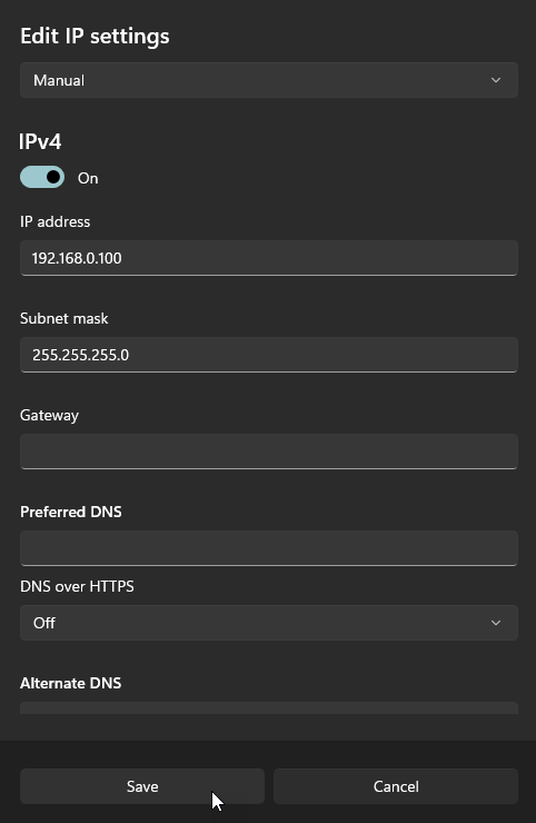
On the computer, go to Settings -> Network & internet -> Ethernet. Next to “IP assignment”, click “Edit”. Change the drop-down field from “Automatic (DHCP)” to “Manual”, toggle “IPv4” to “On”, and save the following (leave everything else as is):
- IP address: 192.168.0.100
- Subnet mask: 255.255.255.0

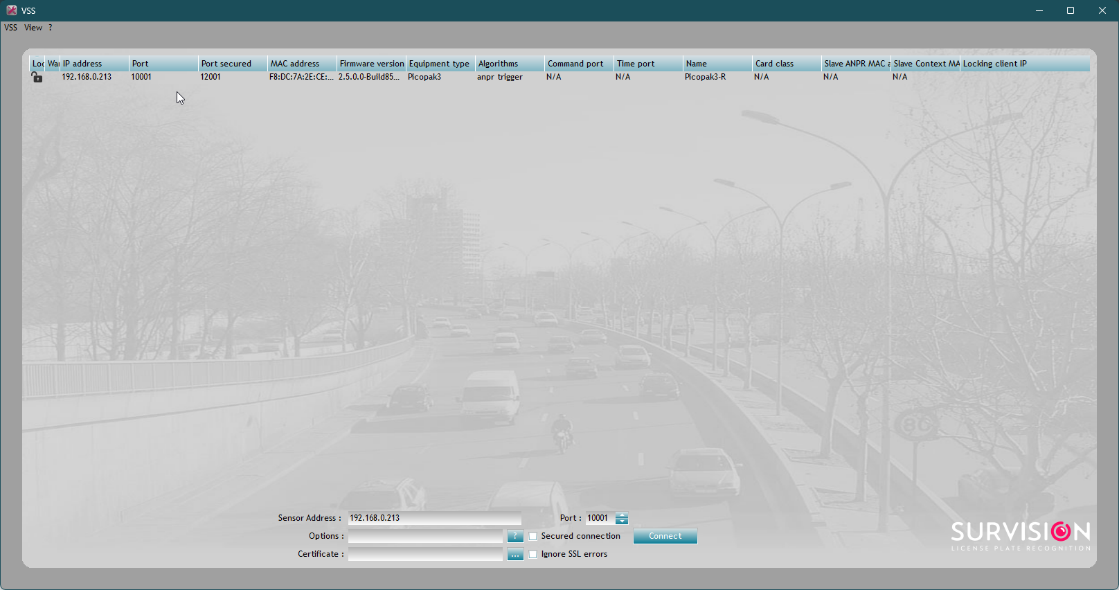
- Open VSS (can be downloaded here) on the computer. You should see the camera appear there; double-click on it to configure it.
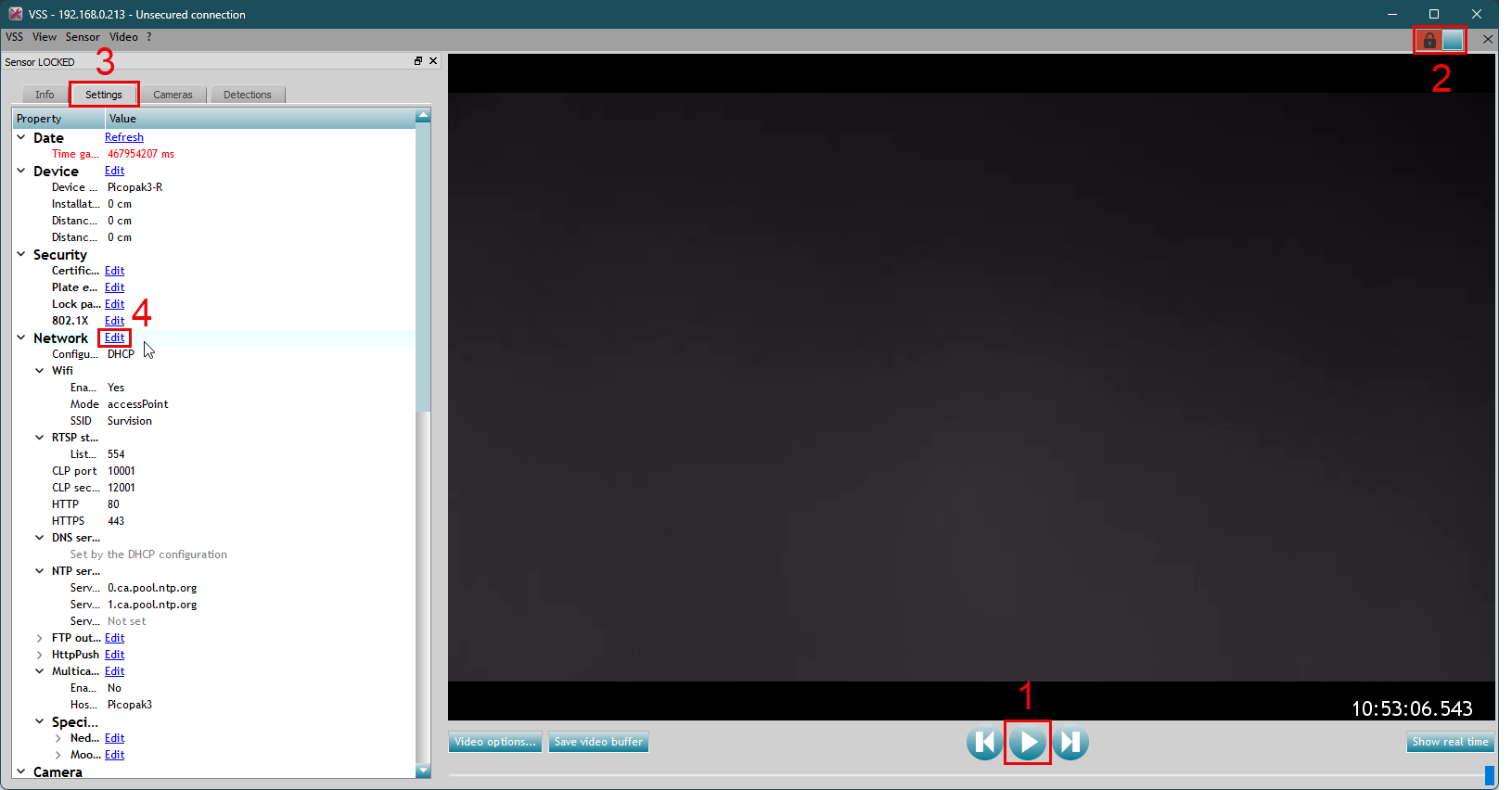
- After opening the configuration page, do the following to start editing the settings:
- Click the "pause" button to stop the live camera feed (this stops the screen from flickering while trying to work).
- "Lock" the device.
- Click on the "Settings" tab.
- Next to "Network", click "Edit".

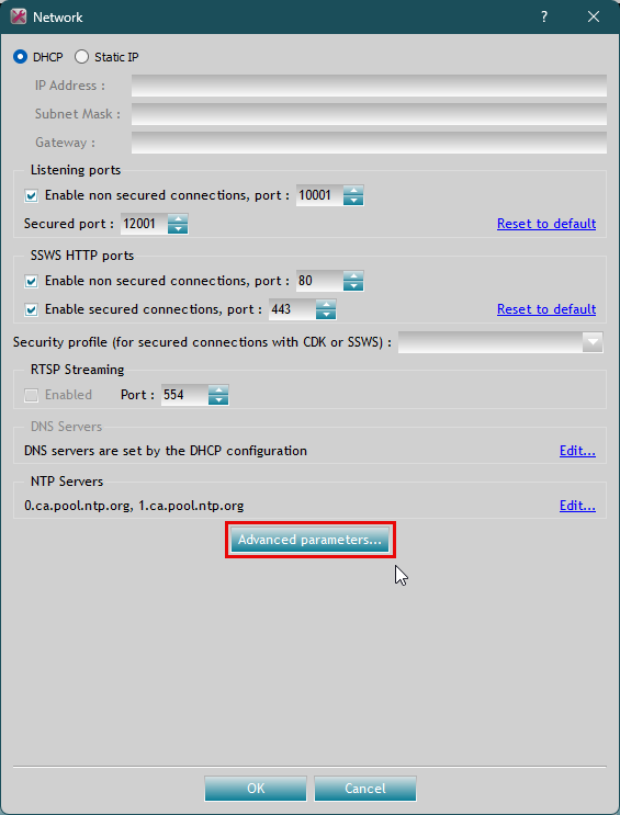
- A box will pop up for configuring the network settings. Leave these settings alone; click "Advanced parameters...".
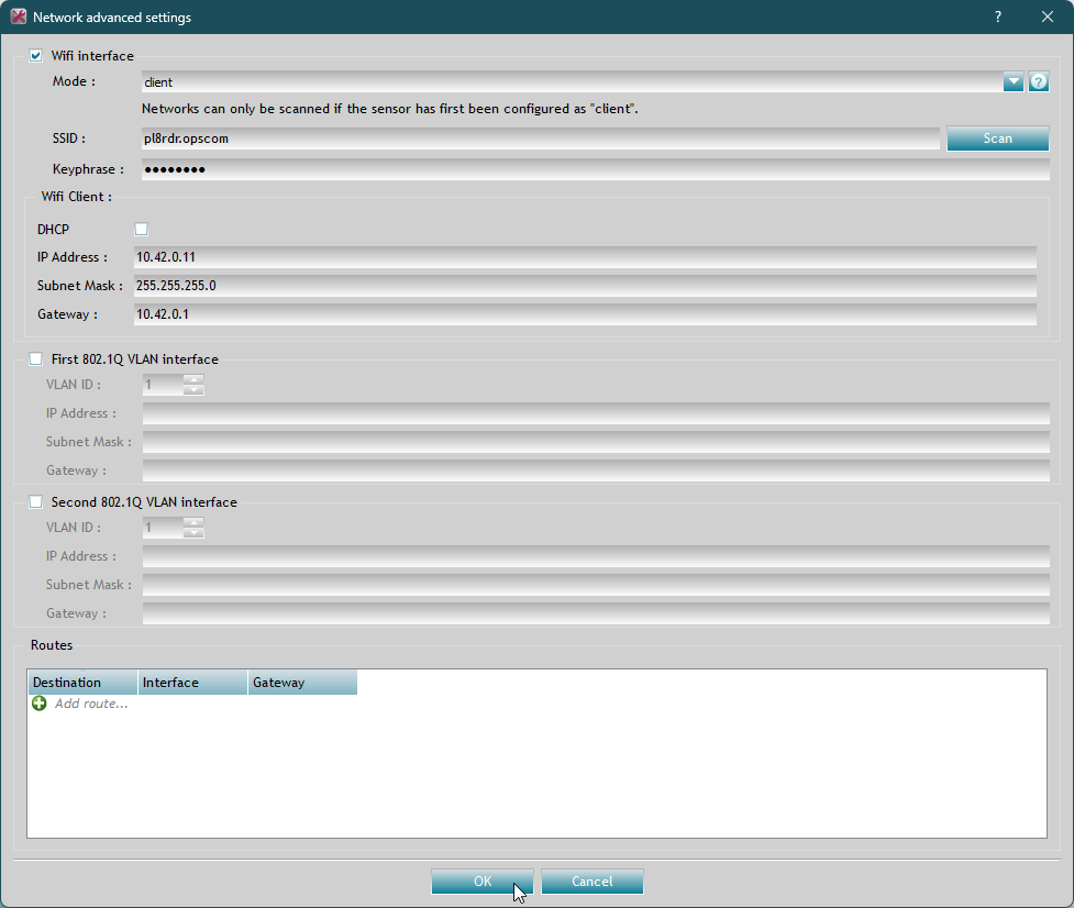
- This is where the Wi-Fi settings are configured. Make sure the settings on this page are set to the following (see image for comparison):
- Wi-Fi interface: on
- Mode: client
- SSID: pl8rdr.opscom
- Keyphrase: T0maha3k
- Wi-Fi Client:
- DHCP: off
- IP Address: 10.42.0.xx, where xx is a two-digit number (usually this should be 10.42.0.11; if client is using more than one camera, they will need different IP addresses)
- Subnet Mask: 255.255.255.0
- Gateway: 10.42.0.1
- Leave everything else blank.

- Wi-Fi interface: on
- Click "OK"; the camera will reboot itself. Wait for it to show up in VSS again before unplugging it. At this point, there should be no further need for an ethernet connection to the camera. You can go back to the computer's ethernet settings and change the the IP assignment back to automatic (DHCP).

Part 2: Configuration Assistant
For this part, you'll need a functioning PL8RDR to broadcast a Wi-Fi hotspot.
- Power on the camera along with a PL8RDR. On a device (either a desktop or mobile device will do), connect to the pl8rdr.opscom Wi-Fi hotspot (password should be T0maha3k).
- Open a web browser and enter the camera's IP address (i.e. what it was set to in the previous part; likely 10.42.0.11) into the address bar. A page should come up with the live camera feed and a button that says "Configuration assistant"; click on this.
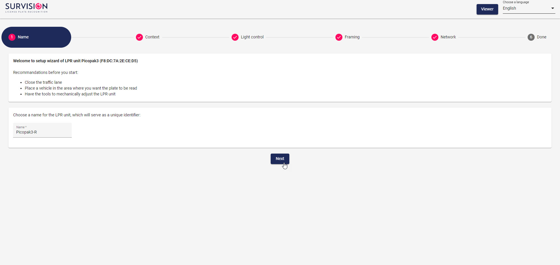
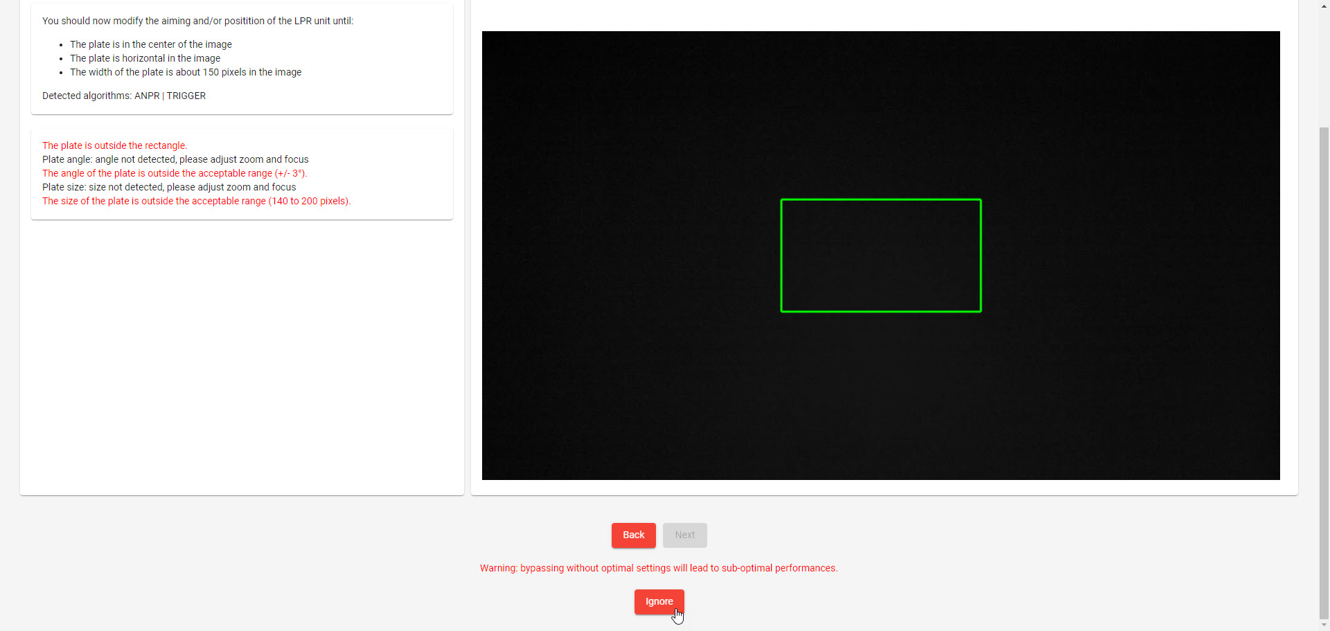
- Proceed through the next five screens as follows:
- Nothing needs to be changed here; click "Next".
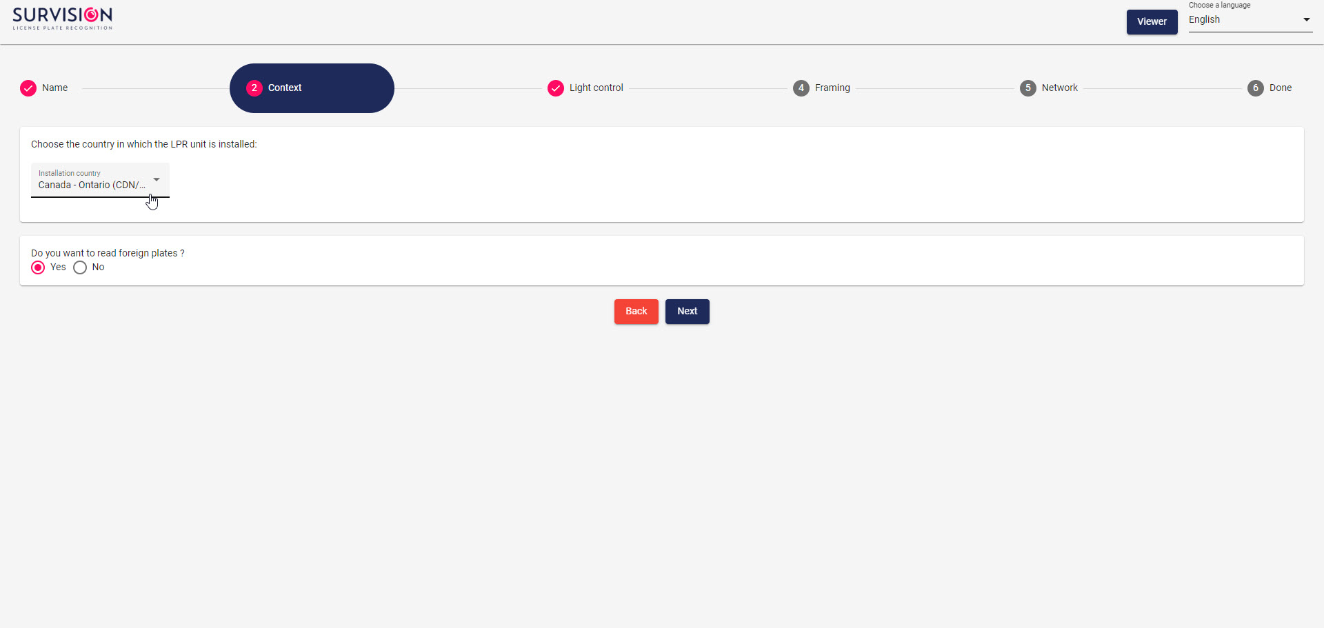
- Set the country and province/state to match the client's location; choose "Yes" for reading foreign plates.
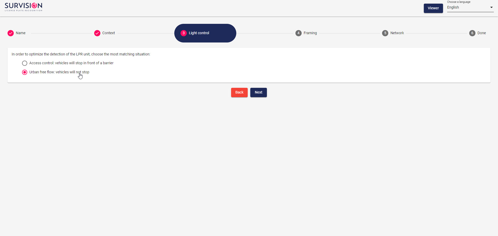
- Set this to "Urban free flow".
- Click "Ignore" at the bottom of this page.
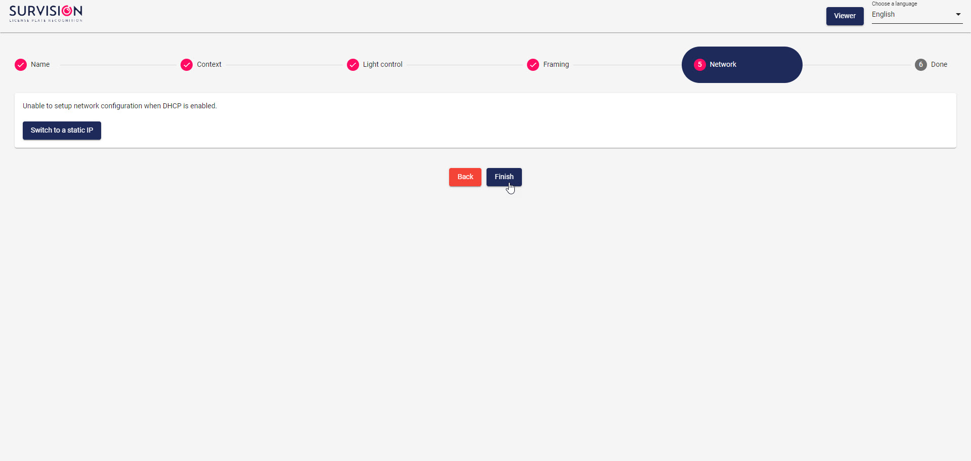
- Nothing needs to be changed here; click "Finish".
- At this point, the window can be closed. The camera should now be fully set up!
- Nothing needs to be changed here; click "Next".

Setting Up a PL8RDR (OnLogic)
Follow these steps to set up a new OnLogic computer for use with OPS-COM as a PL8RDR.
Part 1: Installing the OS
- Before powering it on, make sure the following are plugged into the computer:
- monitor
- keyboard
- mouse
- external hard drive containing OS image
- USB flash drive containing Clonezilla
- Power on the computer. When the OnLogic logo displays on the screen, press Delete to enter the BIOS settings.
- Go to Boot Manager, and choose the option corresponding to the USB flash drive containing Clonezilla.
- Clonezilla will start. Whenever you're prompted to make a choice during the installation process, which option to choose has been documented below:
- Start option: default;
Clonezilla live (Default settings, VGA 800x600) -
Choose language: default;
en_US.UTF-8 English - Keyboard configuration: default;
Keep - Start Clonezilla: default;
Start_Clonezilla - Option: default;
device-image - Device to be written to: default;
local_dev - Partition where image is located: choose option corresponding to external hard drive;
... 930.4G... - Image directory:
Clonezilla Jul_22 - Image directory: current folder should contain image; press Tab;
<Done> - Mode: default;
Beginner - Option: choose
restoredisk - Image file: default (should be only one option);
2024-06-10-21-img - Partition to be written to: default (should be only one option);
... 64.0GB... - Extra parameters: choose
-scr No, skip checking the image before restoration - Action to perform when finished: choose
-p poweroff
- Start option: default;
- The installation process will take a few minutes to complete. Once it is done, the computer should power off. At this point, the installation media (both the external hard drive and USB flash drive) can be unplugged before proceeding to the next part.
Part 2: Confirming PinCntrl Driver GPIO Scheme
This BIOS setting must be enabled to allow the PL8RDR8 to boot up quickly. It should be enabled by default, but it doesn't hurt to confirm it.
- Power on the computer again. When the OnLogic logo displays on the screen, press Delete to enter the BIOS settings.
- Go to Setup Utility.
- Go to the Advanced tab, and enable Expert Mode.
- Go to RC Advanced Menu -> PCH-IO Configuration, and confirm PinCntrl Driver GPIO Scheme (should be at the very bottom of the list) is enabled.
- Press Esc repeatedly to exit the Setup Utility. You can choose Yes to discarding changes if PinCntrl Driver GPIO Scheme was already enabled. At this point, the computer can be shut down.
Part 3: SIM Card
- Go to the Control Center for the SIM cards, click on Devices, click on the correct SIM number, and click Edit.
- Enter the correct settings; they can be copied from a working SIM card from another client's setup.
- Once the SIM card is properly set up, insert it into the PL8RDR. This requires unscrewing the plate from the bottom of the computer and lifting out the cell modem to access the SIM card slot underneath.