Tattile LPR Camera
- Powering a Tattile Mobile LPR Camera
- Configure Tattile LPR Camera
- Connect to a Tattile Mobile Camera
- ANPR Setup Checklist -Tattile
- ANPR Tattile Camera Screenshots
- Static LPR Checklist - Tattile
- Updating Tattile Camera Firmware
- Trobleshooting Tips
Powering a Tattile Mobile LPR Camera
Standard Hardware
There are several pieces of gear that comprise the OPSCOM LPR system. A typical system includes the following items:
-
2-Tattile Mobile LPR Cameras with one connector cable per camera
-
1-PL8RDR Device 4G/LTE
-
1-4G/LTE Tablet
-
1-3” Bluetooth printer
-
1-RAM Universal No-Drill Tablet Vehicle Mount & Accessories
Each Mobile LPR camera will need a cable built to accommodate communication between the PL8RDR device and the camera.
Cables are best to be custom built in order to suit the logistics of what vehicle is being used and where the camera is located on the vehicle.
Note: It is best practice to have the proper amount of cable so no coiling or stretching of the cable is required.
Standard Power Cable
Used to supply power to the camera. The camera will connect to the PL8RDR computer wirelessly.
Parts Required for Each Cable
-
BINDER M16 99-5672-19-08 series 423 connector (part code T18654)
-
Power cable - RED/BLACK cable 0.50 mm cut to the proper length to accommodate the distance from the cable to the power source
-
an inline fuse is suggested
-
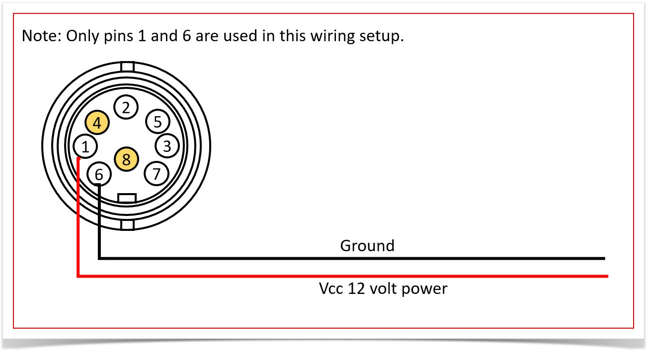
This is the front view; holding the connector by the wires and viewing the terminals.
Advanced Cable For Troubleshooting
The following diagram represents how the cable should be wired in an advanced setup where the camera communicates with the PL8RDR through a standard ethernet cable.
This is more likely to be used in troubleshooting rather than typical operation.
Parts Required for Each Cable
-
BINDER M16 99-5672-19-08 series 423 connector (part code T18654)
-
Ethernet CAT5 cable cut the proper length to accommodate the distance from the PL8RDR to each Camera
-
Power cable - RED/BLACK cable 0.50 mm cut to the proper length to accommodate the distance from the cable to the power source
-
NOTE: CAT cable can supply power on unused pair
-
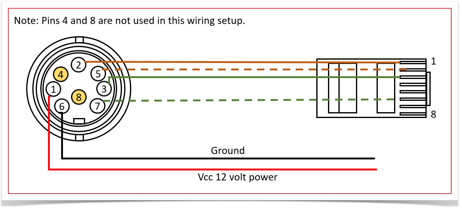
This is the front view; holding the connector by the wires and viewing the terminals.
Configure Tattile LPR Camera
For the Survision LPR Camera configuration, go to Survision LPR Camera Configuration
Connecting Wirelessly
The first step is to connect to your PL8RDR device via wireless connection. To do so bring up your systems Network Settings by following the steps below
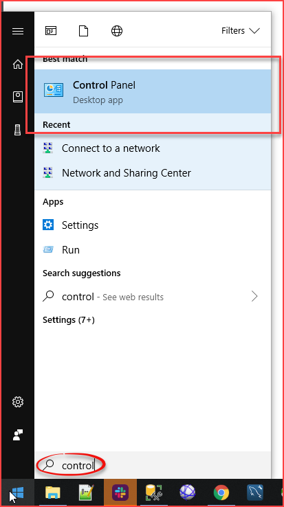
Click on the Windows Home Button and start typing Control Panel. It should pop up under Best Match as you are typing.

Click on Control Panel to access your Computer's Settings.
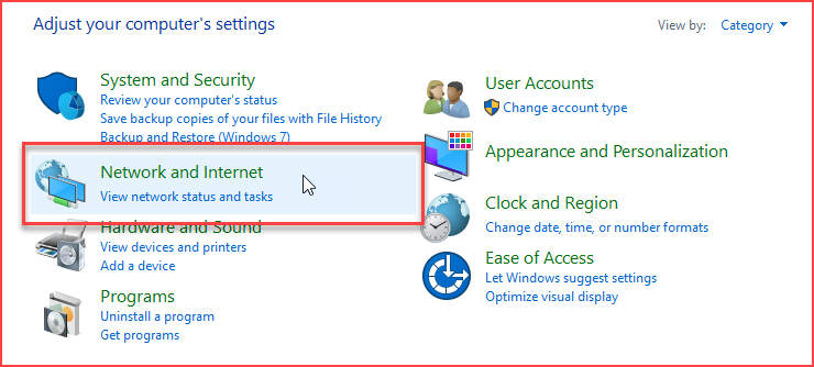
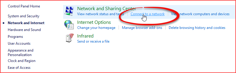
A list of all available configuration items will appear. Click on Network and Internet.
In Network and Sharing Center settings click on Connect to a Network.
Connect to pl8rdr.opscom
First make sure Wi-Fi is turned on by clicking the network icon at the bottom right of your screen. You will see a list of networks available to you. In this case we are looking for the pl8rdr.opscom network.
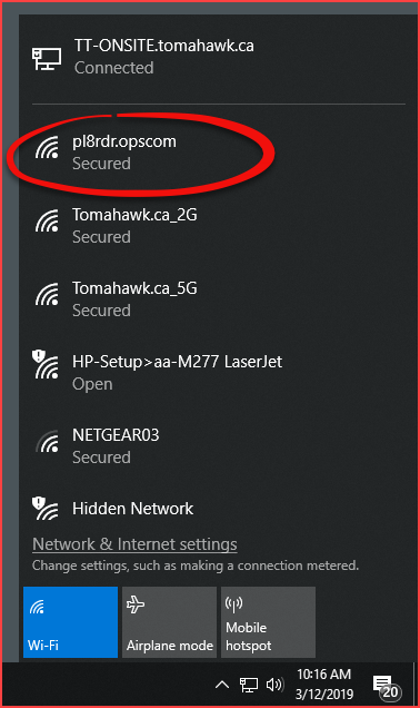
Clicking the pl8rdr.opsom network will open a screen where you can click on Connect to join the network. You can also utilize the Connect automatically check box do avoid having to connect manually each time.

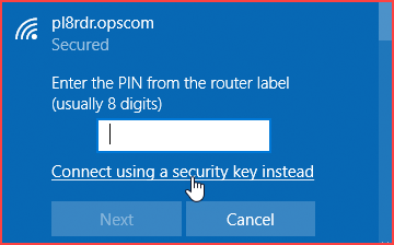
Since the network is secured a password/PIN is required to connect. Click on Connect using a secure key instead to bring up a seperate password entry field.
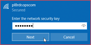
Enter the password into the empty field and click on Next.
Note: The password is provided by OPSCOM. If you do not know your password please contact support@ops-com.com
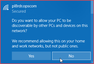
You will be prompted to allow your PC to be discoverable by other PCs on this network. Click No as you do not want this connection to be open to other PC's.
You will see the connection status below the pl8rdr.opscom network appear as Connected.

Connect to the Camera
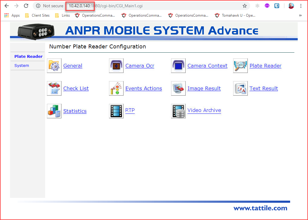
Now you can open a browser and enter the IP address of your camera in the go to field.
You will also need to follow the IP address with a port number. For mobile cameras the port number is 1080 therefore the URL would look like this:http://[IPAddress][colon][port number] as in the example below you can see the URL as http://10.42.0.140:1080
If you do not know the IP address of your camera see How to Find the IP Address of your Camera found below.
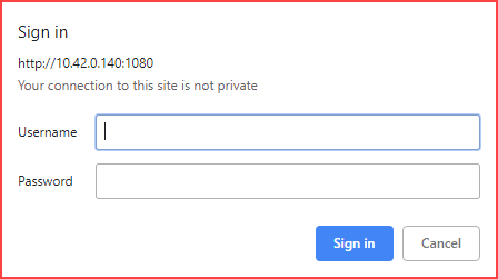
You will be prompted for a Username and Password.
| Username | Password |
|---|---|
| superuser | superuser |
The main Number Plate Reader Configurations page will appear. Note the IP address and port number in the browser as well as the rest of the URL that will resolve automatically.
Naming Mobile Cameras
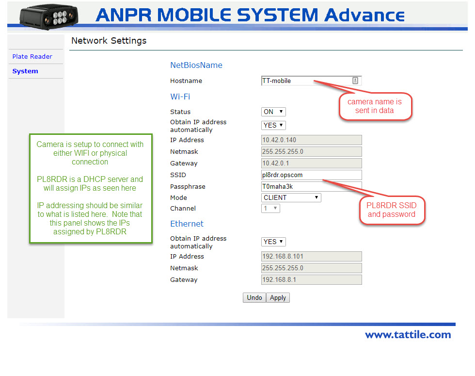
Under System → Network you can name the camera(s) appropriately.
- Mobile-L = Drivers side
- Mobile-R = Passenger side
How to Find the IP Address of your Camera
On the handheld unit go to main menu and tap on LPR Scanning.
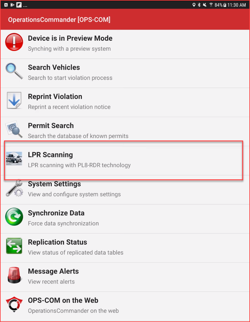
Once in the LPR screen tap on Status near the top right of the screen.
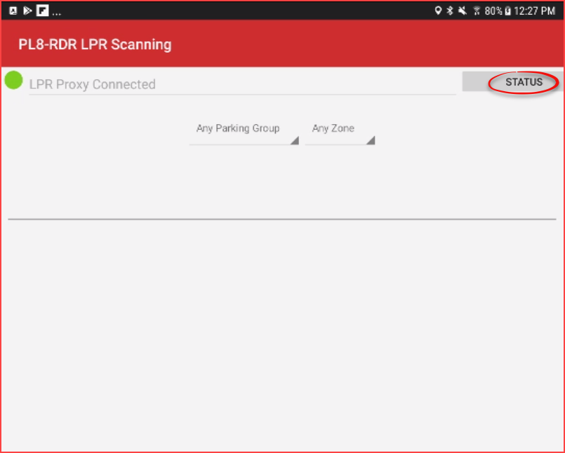
You will see a list of connected devices. The device Type should be Tattile camera wifi.
Please note that due to new cameras coming onto the market, your PL8RDR may list a camera as an unknown device.
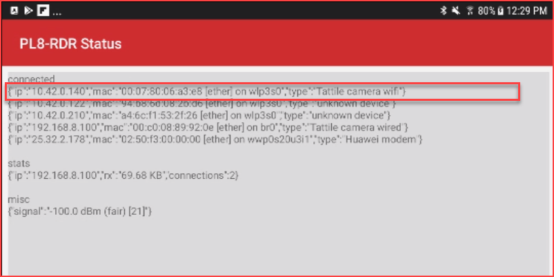
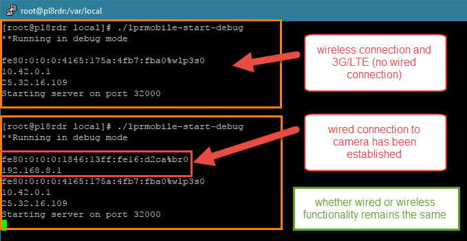
In this case the cameras IP address was 10.42.0.140. Enter the IP address for your device with port :1080 into the browsers URL and hit Enter.

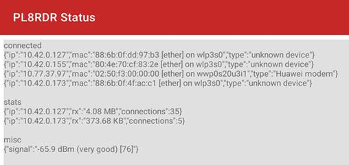
The below screen shot is taken after the cameras have read some plates.
Notice the "stats" entry which clearly lists the camera IP addresses.
Also note that sometimes the system is not able to determine which device is a camera.
Connect to a Tattile Mobile Camera
First Time Connection
Power up the camera and give it a few minutes to fully boot up.
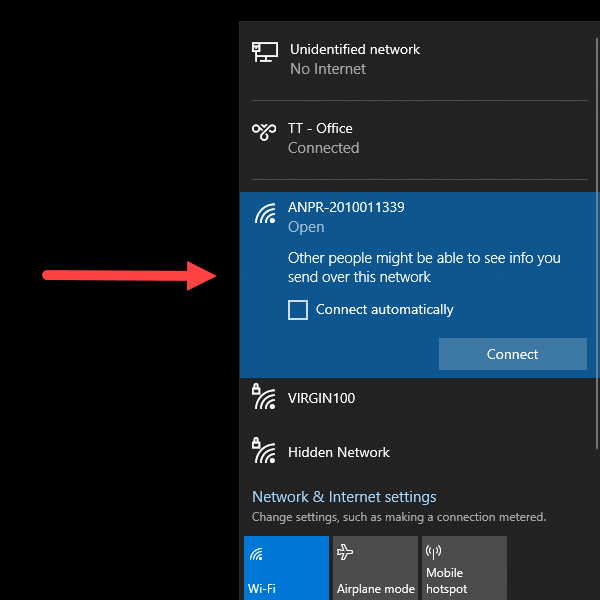
At that point you will see the camera in your network connections list.
Note the network name reflects the serial number of the camera In this case ANPR-2010011339
Click connect to establish a connection between your computer and the camera's hotspot.
The standard IP address for the camera coming from the factory is set at 192.168.150.1
You will also have to put the port number in your URL when trying to connect through your browser.
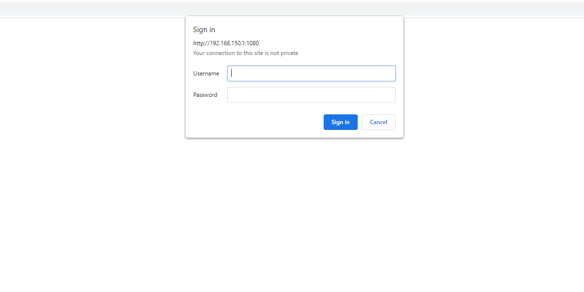
Open a browser and enter the camera IP and port into the address bar. In this case it will be 192.168.150.1:1080 (Where 192.168.150.1 is the camera IP and 1080 is the port number)
You will be prompted to enter a user name and password.
Username superuser
Password superuser
You will then be directed to the Plate Reader Tab of the camera configuration.
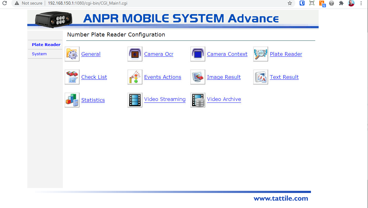
There are Specific areas that you will need to configure.
On the Plate Reader tab you will edit:
General Settings
Event Actions Also known as TCP Events
JPEG Image Header Configuration
Plate Reader Settings
On the System tab you will edit:
Network Settings
It is very important to edit the network settings properly and in a proper sequence. If for example you configure the camera to connect to the PL8RDR but forget to set it to assign an IP (DHCP) and save the changes. You will not be able to log in to the camera wirelessly.
Related Video
This video shows the process described above as to how to log in to the camera for the first time.
ANPR Setup Checklist -Tattile
Initial Setup
| Wired | Wireless | Port |
|---|---|---|
|
192.168.0.21 |
SSID: Anpr-###### |
1080 or 8081 |
Initial Access to the Camera
Yet another setup trick is to login to the device initially using WIFI.
The device will need to be plugged into a network hub that is connected to a DHCP server
- change the wired IP to Obtain Automatically
- later in the process we do this anyways
- device will reboot
- reconnect using WIFI and record the wired IP that was assigned to the device
- generally a device will be assigned the same IP each time it boots
- you should now be able to connect to the listed wired IP
- disconnect your wifi connection
This is useful since often your computer will become confused about where to send packets. Using the wifi connection is good for configuration, but accessing other online resources may be problematic with the second connection. Once the wifi is disconnected all configuration can be performed through the wired IP.
Connecting to PL8RDR from tablet or camera
WIFI: pl8rdr.opscom / T0maha3k [10.42.0.1]
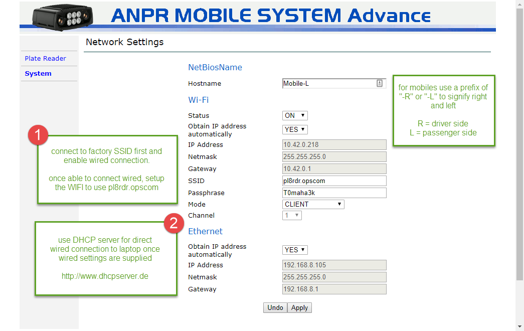
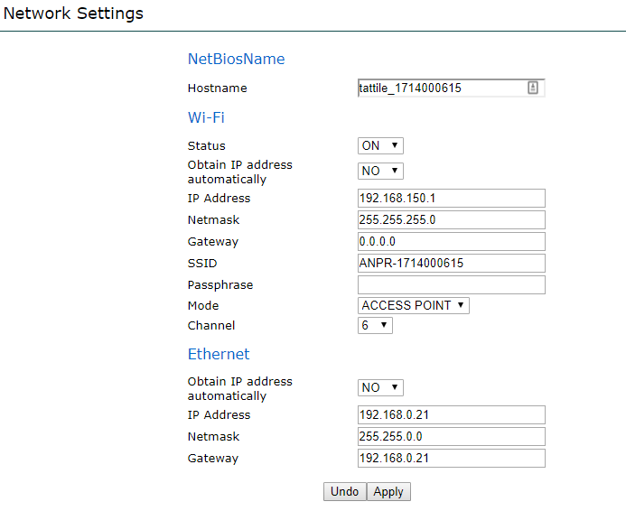
System - Network Settings
Changes on this panel will reboot the device.
This work is usually done by OPSCOM support.
Details are here to help those clients that are doing initial configuration themselves.
* Suggested that WIFI settings be changed last unless you have a local DHCP server setup.
During setup the device reboots several times, any changes to WIFI settings may make it more difficult to connect to complete configuration.
- * connect wireless and setup wired connection first, then connection may be easier
- device reboots numerous times during setup
- DHCP server software: http://www.dhcpserver.de - dhcpsrv2.5.2.zip (extract to C: )
- setup computer with LAN 192.168.8.1 and use that for IP assignment
- camera will connect to computer to obtain IP address
- Hostname: Mobile-R | Mobile-L (that way we know which is the Right / Left camera)
System - Time Sync
Changes on this panel will reboot the device.
- not terribly important as the PL8RDR records the time of the event not the values sent by the camera
-
Time Server (use your own or one of these)
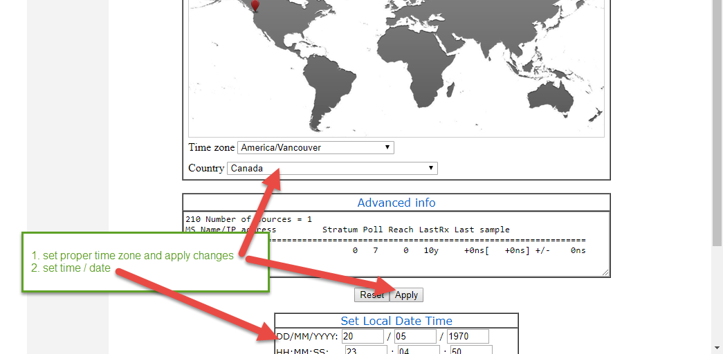
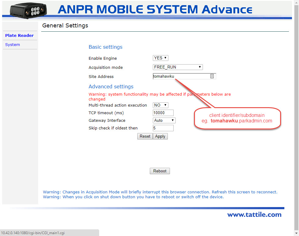
Plate Reader - General Settings
- should always be the CLIENT_ID (no spaces)
-
eg. OC_TOMA
-
NOTE: This graphic shows and old implementation. The text in this sample should be only: OC_LIONS
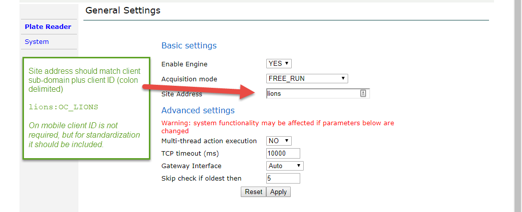
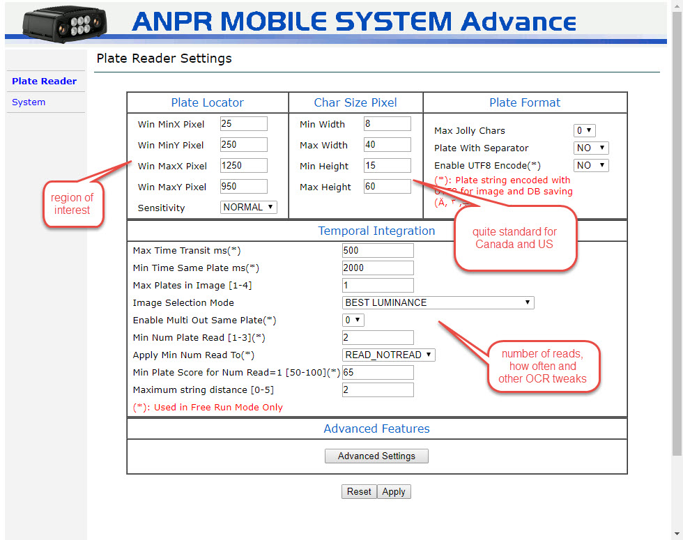
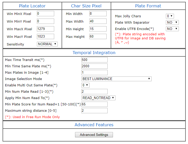
Plate Reader - Plate Reader
Changes on this panel will reboot the device.
- create a buffer around the capture area
- the listed settings are factory defaults (except Locator) and should work with minimal issues
- for mobile bounding region should be set to a lower area since plates will rarely be at the top of the image
- leave a gutter around the bounding area of at least 30 pixels
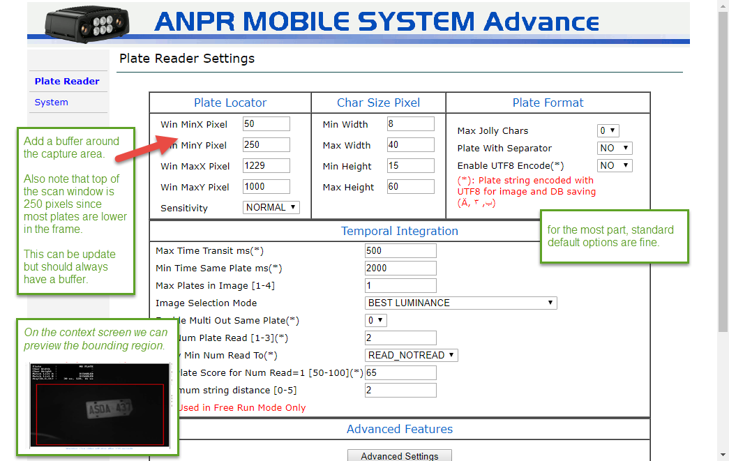
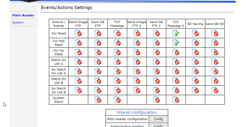
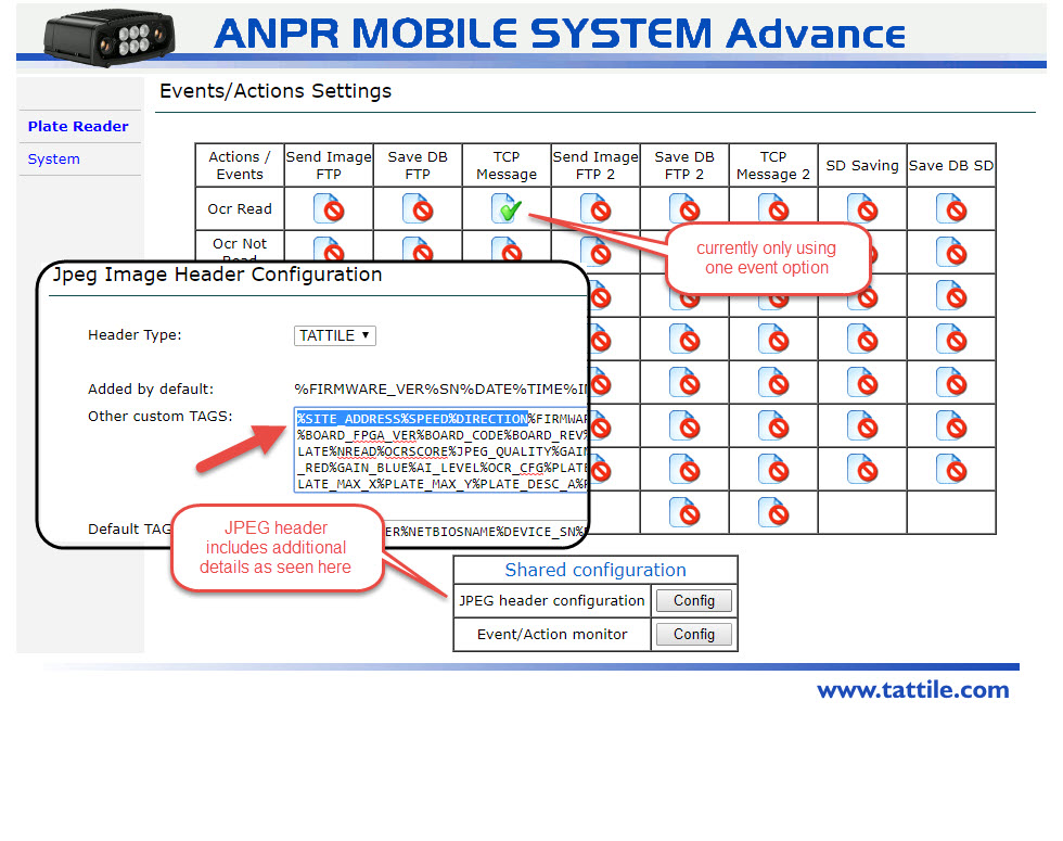
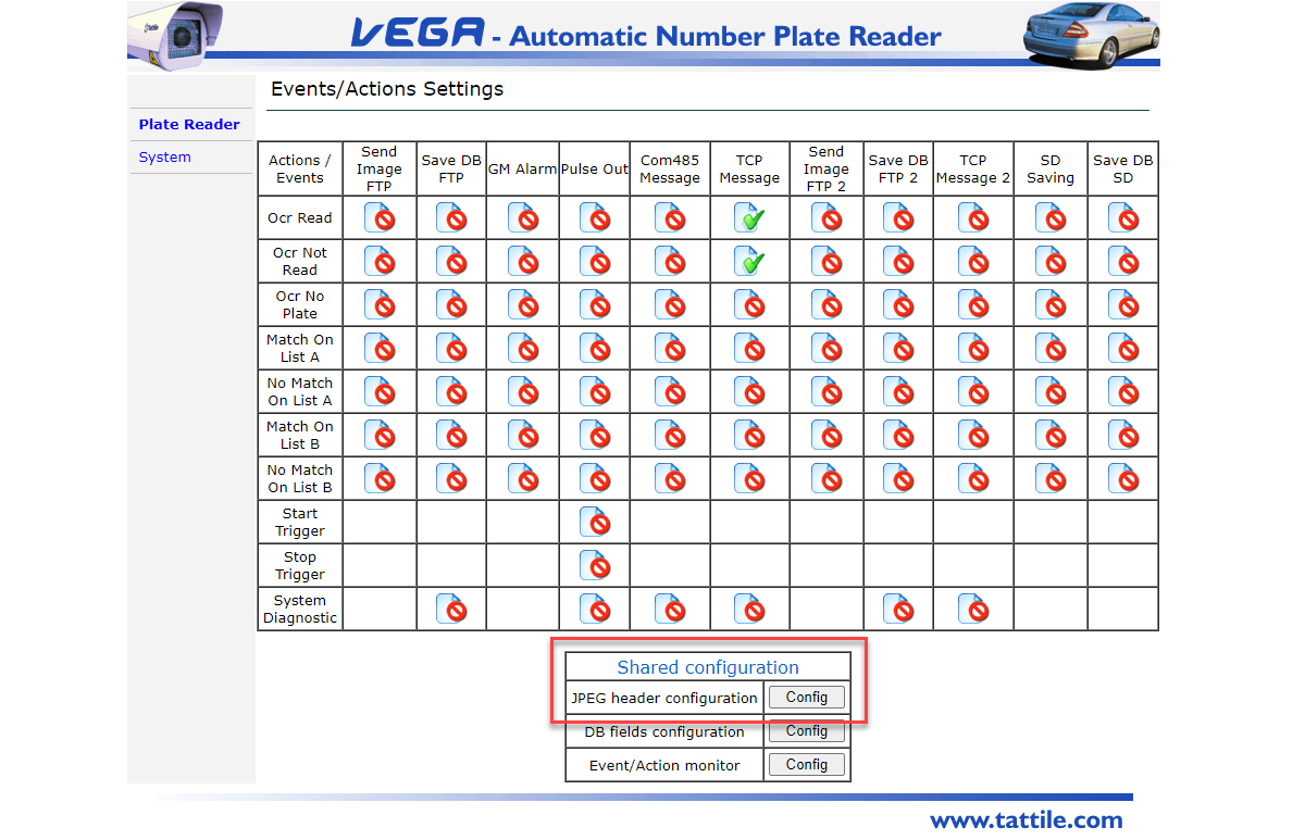
Plate Reader - Events Actions
- (Mobile) there are 4 options; 2 for wired and 2 for wireless
- 1 each are READ results; 1 each are NO_READ results (vanity plates)
- %SITE_ADDRESS is not important for Mobile but listed here for standardization
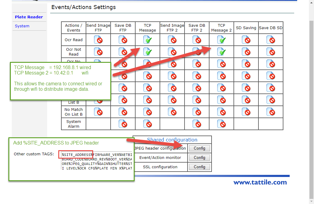
During configuration set wired TCP Message connection as Enable=No
Cameras leaving Tomahawk's office will be setup to use wireless only. Configuring wired settings can help with troubleshooting in the future.
Events - Specific
-
2 x READ - wired (192.168.8.1) & wireless (10.42.0.1)
-
%PLATE_STRING%IMAGE_BW%IMAGE_COL%PLATE_MIN_X%PLATE_MIN_Y%PLATE_MAX_X%PLATE_MAX_Y
- Server IP: 192.168.8.1 Server Port: 32000
-
%IMAGE_BW sends the thumbnail image (required)
%IMAGE_COL sends the context image (not required)
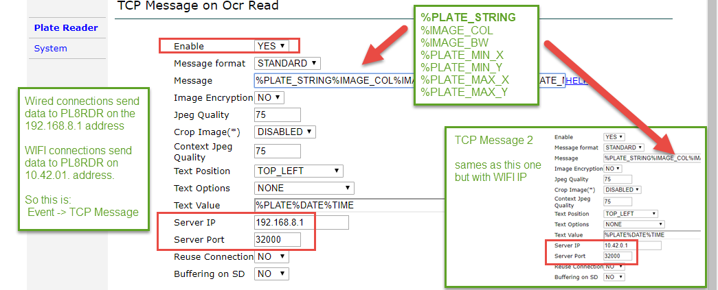
-
2 x NO_READ - wired (192.168.8.1) & wireless (10.42.0.1)
-
%PLATE_NOT_READ%IMAGE_BW%IMAGE_COL%PLATE_MIN_X%PLATE_MIN_Y%PLATE_MAX_X%PLATE_MAX_Y
- Server IP: 10.42.0.1 Server Port: 32000
-
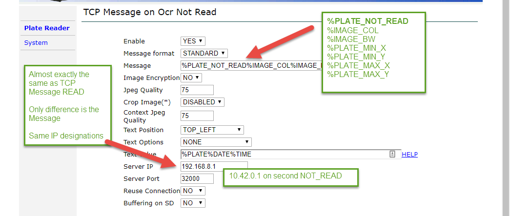
Wireless Only with Wired Disabled
The final screen should look as shown below. "TCP Message" is setup (disabled) for 192.168.8.1 and "TCP Message 2" is setup (enabled) for 10.42.0.1
We are shipping cameras with wireless configured and wired ready to be enabled if needed; as of spring 2020
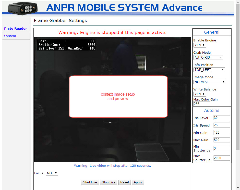
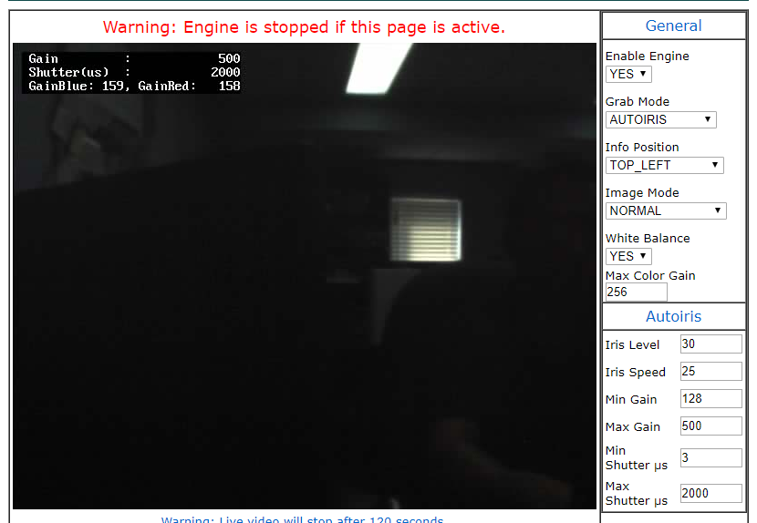
Camera Context
- likely not necessary to make changes in this area
- adjust; iris, gain, shutter
Plate Reading Quick Test
You should now be able to go to Plate Reader - Text Result and hold a plate in front of the camera to confirm operation.
Further testing is suggested with a PL8RDR system.
ANPR Tattile Camera Screenshots
|
|
|
|
|
|
|
|
|
|
|
|
|
|
|
|
Static LPR Checklist - Tattile
Required fields are:
- IP Address
- NetMask
- Gateway
- DNS Server (8.8.8.8 can be used)
Time Server (use your own or one of these)
- 0.us.pool.ntp.org
- 1.us.pool.ntp.org
- 2.us.pool.ntp.org
- 3.us.pool.ntp.org
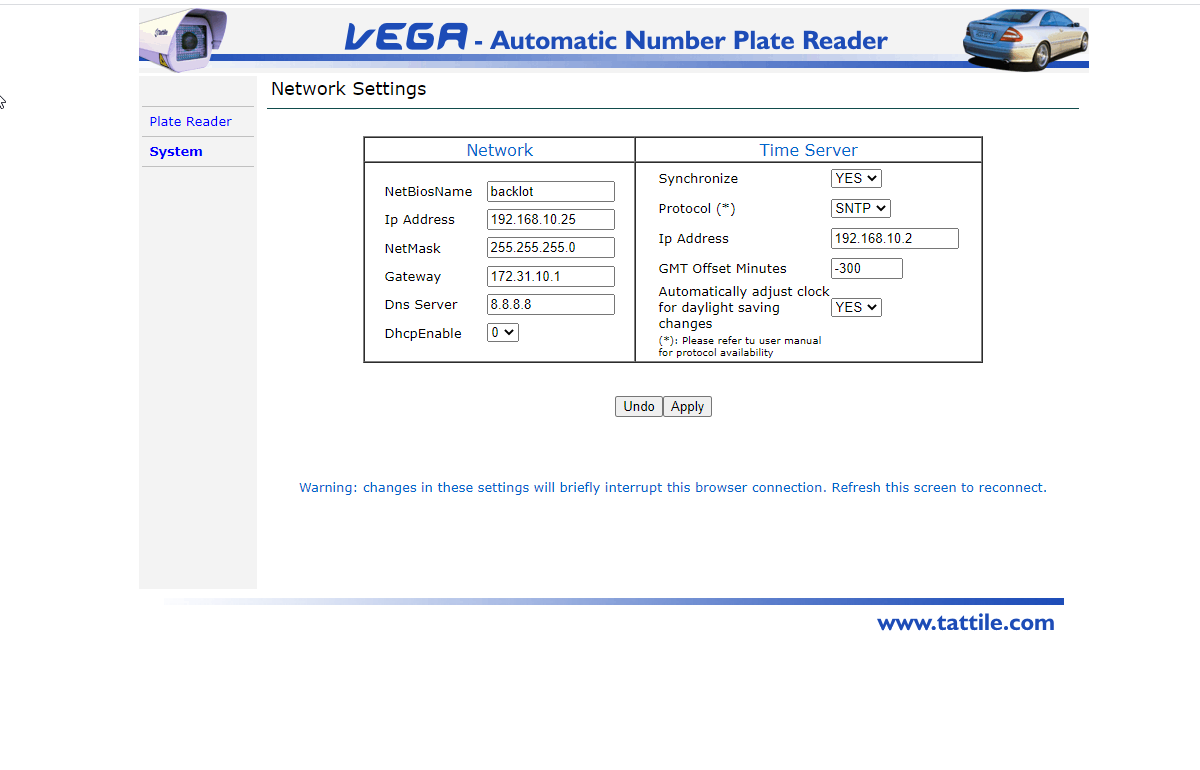
System - Time Sync
Changes on this panel will reboot the device.

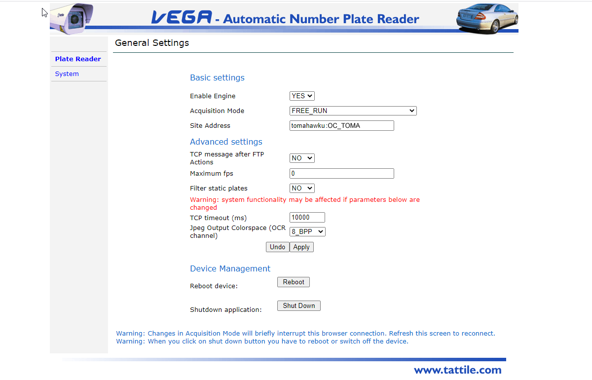
Plate Reader
General Settings
Configure the site address which should be client_subdomain : CLIENT_ID (no spaces)
Your subdomain is the first part of your OPSCOM.com web portal address.
As an example, the demo Tomahawk University is located on the web at tomahawku.OPSCOM.com and the entry here would be tomahawku:OC_TOMA
If you are unsure of the client_subdomain or CLIENT_ID please contact OPSCOM support
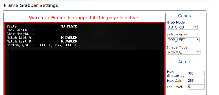
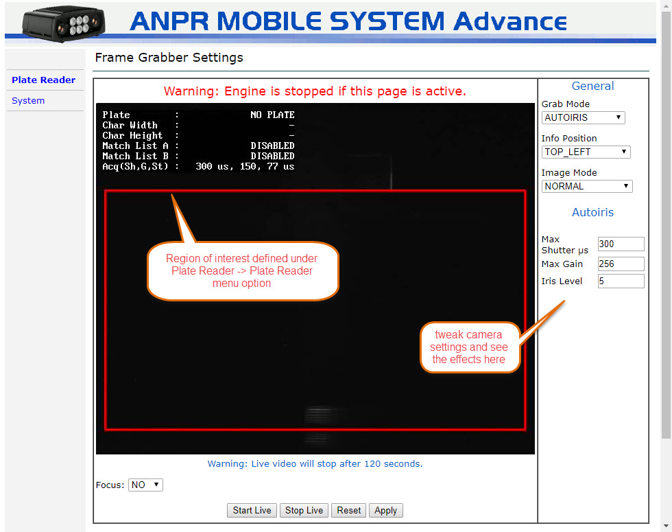
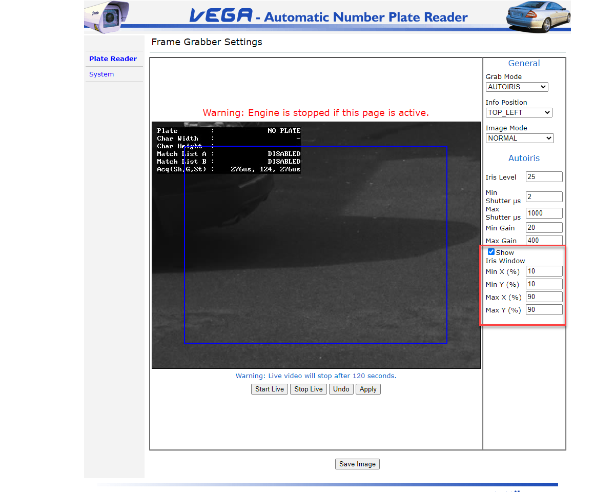
Frame Grabber Settings
Iris Bounding Region
- For faster plate reads you can adjust the capture area
- Typically factory defaults to full frame
- For PL8RDR, it is necessary to create padding around the capture area (minimum 30 pixels)
- In this example we have modified the factory defaults by 10% all around
- Click on Show Iris Window to see the bounding box
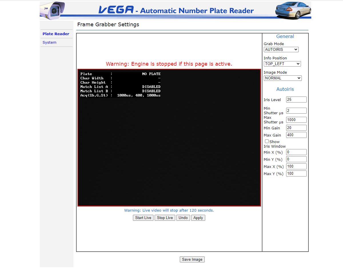
Camera Auto Iris (advanced)
As directed by OPSCOM support staff adjustments may be made to specific camera properties.
- iris
- gain
- shutter speed
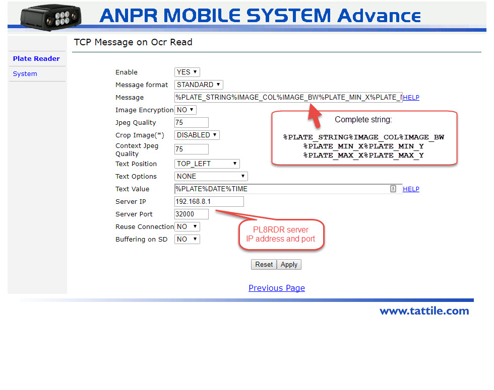
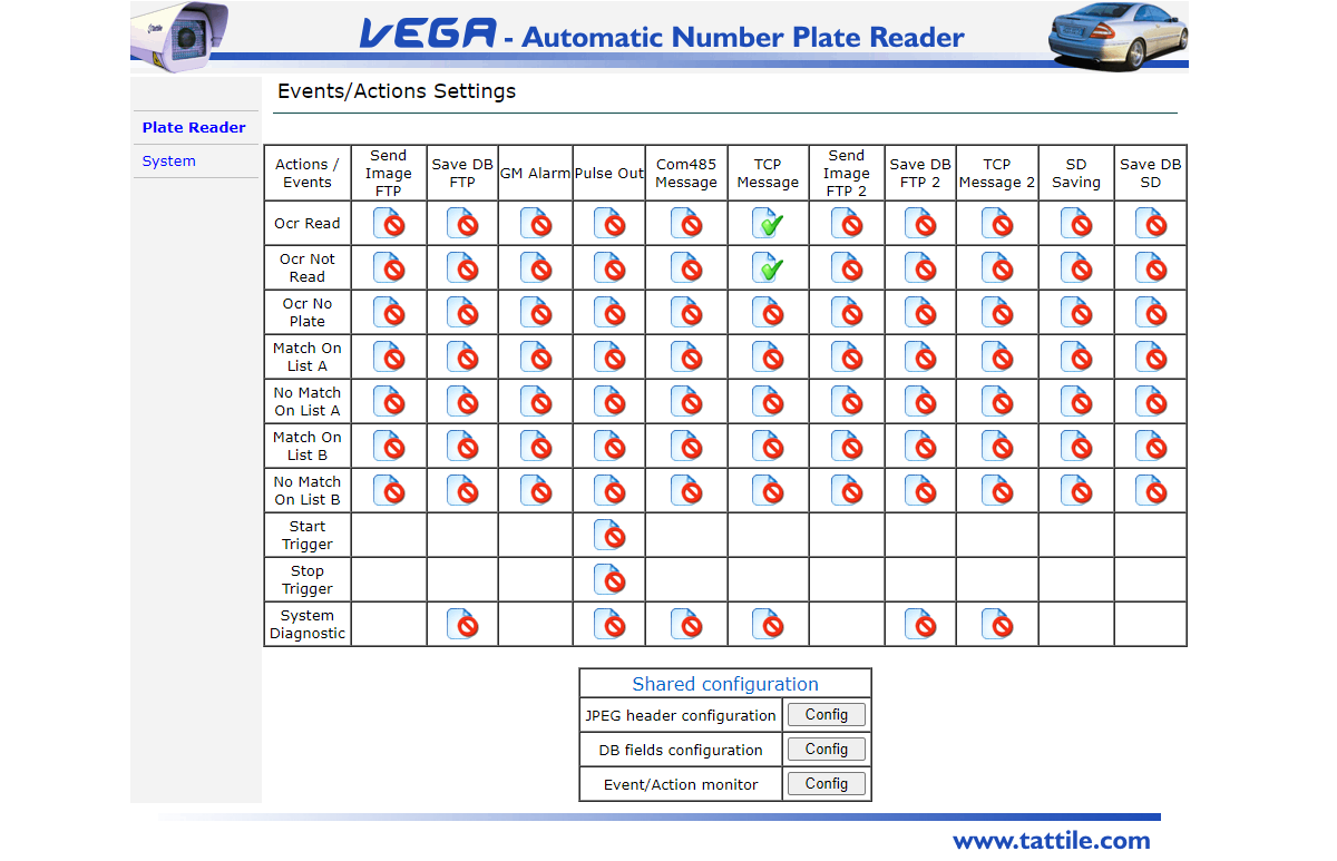
Events Actions
- There are 2 TCP Message options:
- Ocr Read
- Ocr Not Read (vanity plates)
Ocr Read Events
-
READ (key fields)
- Enabled = Yes
-
Server IP = 159.203.51.51
- Server Port = 32000
-
Message = %PLATE_STRING%IMAGE_BW%IMAGE_COL%PLATE_MIN_X%PLATE_MIN_Y%PLATE_MAX_X%PLATE_MAX_Y

|
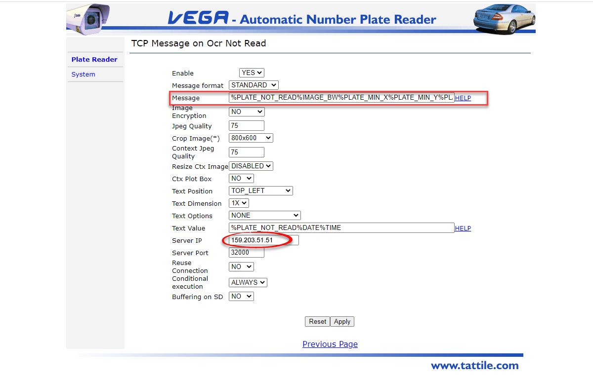
Ocr No Read Events
-
NO_READ (key fields)
- Enabled = Yes
-
Server IP = 159.203.51.51
- Server Port = 32000
-
Message = %PLATE_NOT_READ%IMAGE_BW%IMAGE_COL%PLATE_MIN_X%PLATE_MIN_Y%PLATE_MAX_X%PLATE_MAX_Y
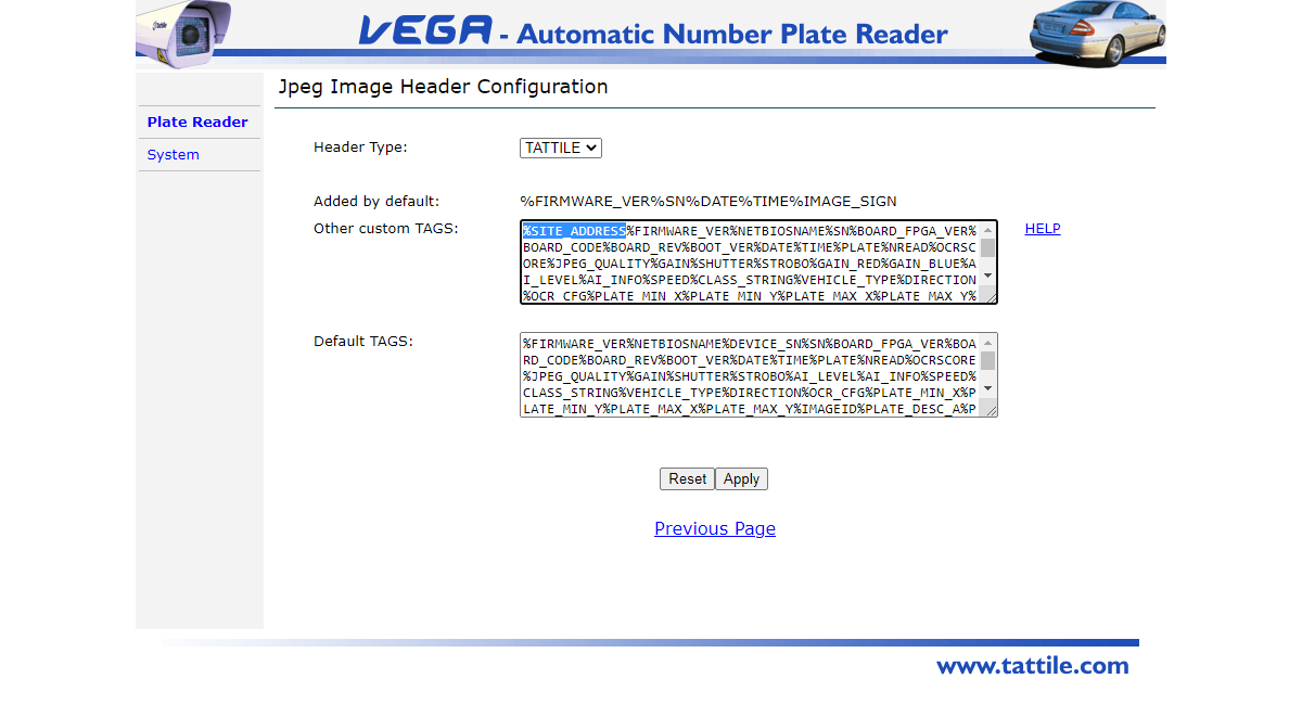
JPEG Image Header
Select to edit the configuration by selecting the Config button
Add %SITE_ADDRESS to the field Other custom TAGS
Updating Tattile Camera Firmware
Justification for Firmware Updates
There are two purposes behind updating the firmware of the LPR camera. One would be to simply update the existing firmware. The other is changing the firmware based on your specific region. There is specific firmware tailored to the region in which you are using the camera. There would be firmware specific to the state of California and it's surrounding states that would be optimized for reading plates in those states as opposed to plates in Florida for example, Firmware updates allow you to update the entire system. This instruction applies to ANPR Mobile cameras.
How to Update
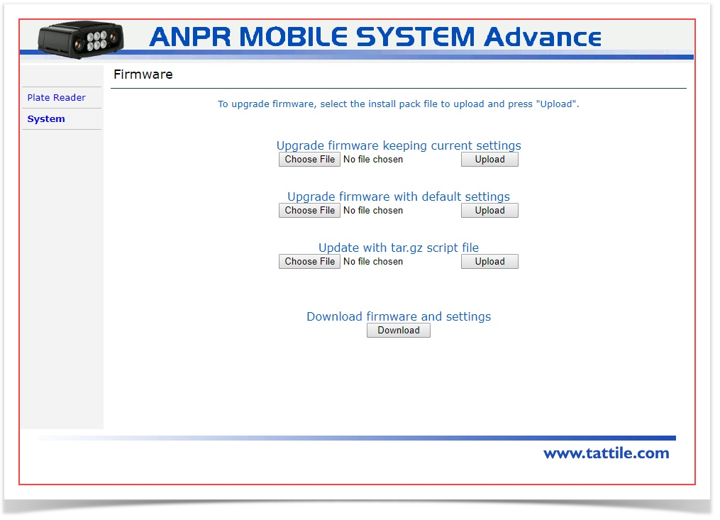
Two updating methods are available:
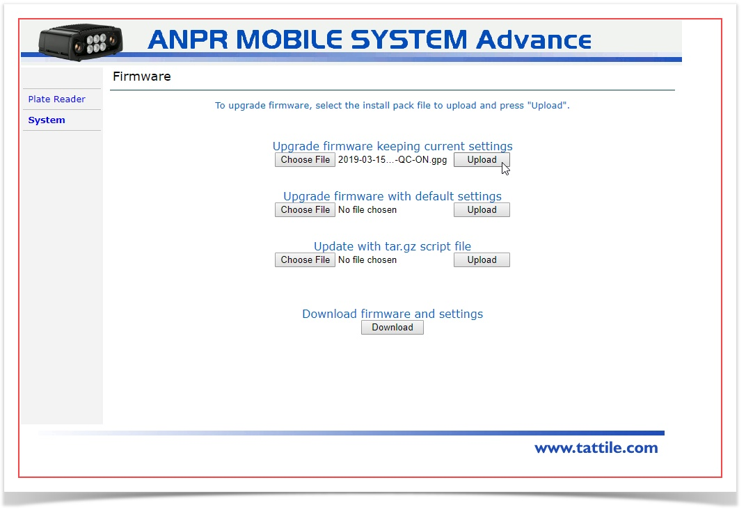
- Upgrade firmware keeping current settings: in this section, the update is carried out without changing the previously configured parameters.
Press the Browse button and select the update file from the PC file list. Once this file has been selected, press the Upload button and confirm the operation. When update completes, the User is asked to reboot the ANPR Mobile machine by pressing the Reset button displayed on screen. - Upgrade firmware with default settings: in this section, the upgrade is carried out by deleting all user-defined parameters and reloading the default settings of the new .BIN file just loaded using the Browse and Upload command sequence.
This procedure is the same as the one previously described.
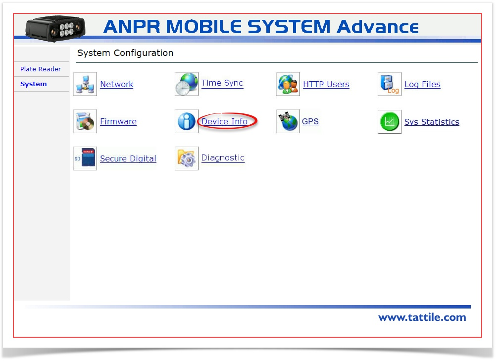
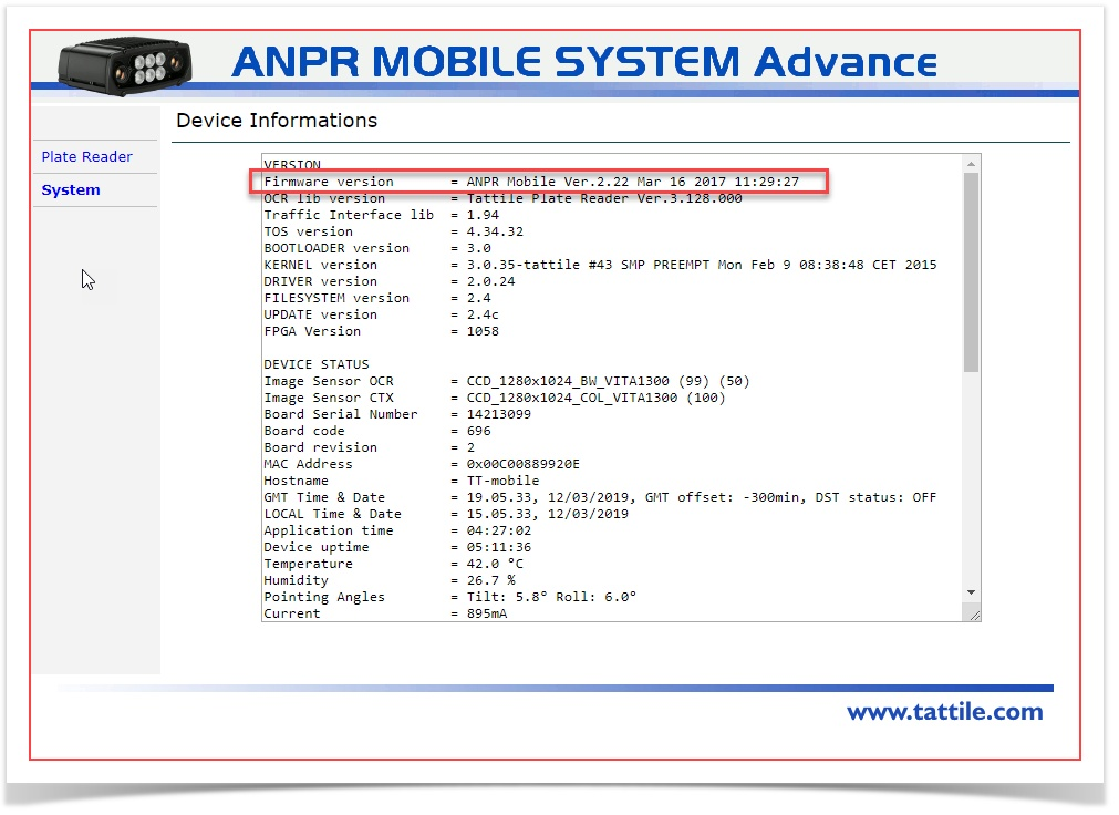
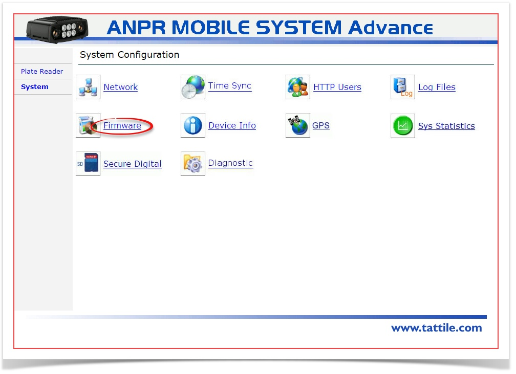
How do I find my current firmware version?
- Go to the System tab of the camera configuration screens. Look for Device Info.

- Click on Device Info to bring up the Device Info screen. The firmware version is the first line in the information list.

- If it is established that the firmware is out of date, go back to the system tab and look for the Firmware menu item.

- Click on Firmware to bring yo to the update page.

- If you are in the process of upgrading the firmware there are two main factors to consider.
You are either starting with a new camera in which case you will upgrade with default settings or, if you have a previously configured camera you will be upgrading the firmware keeping current settings.

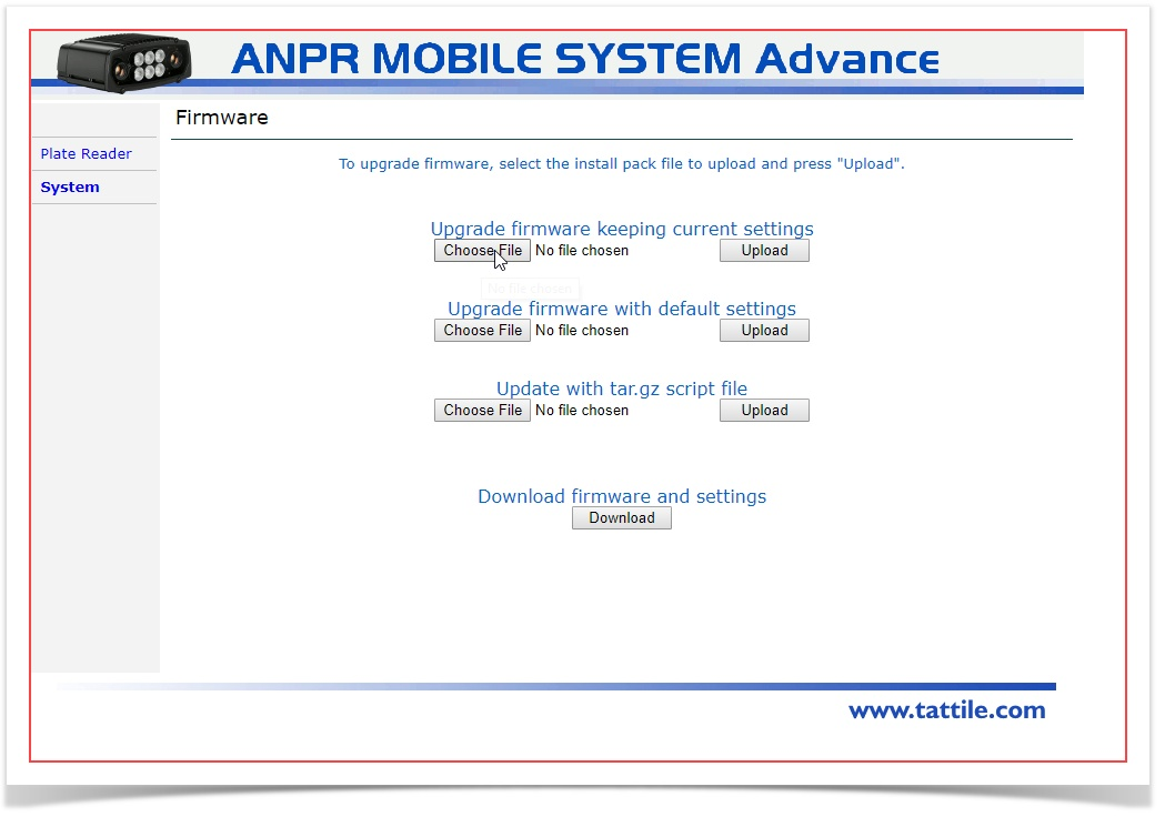
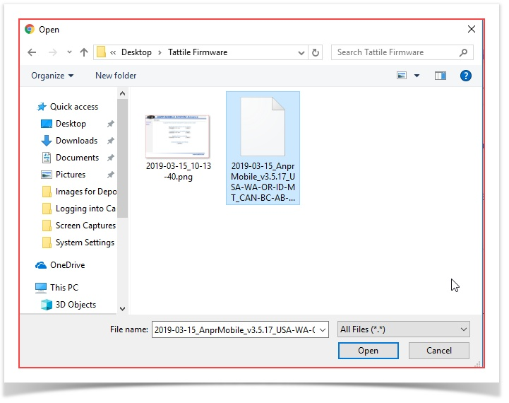
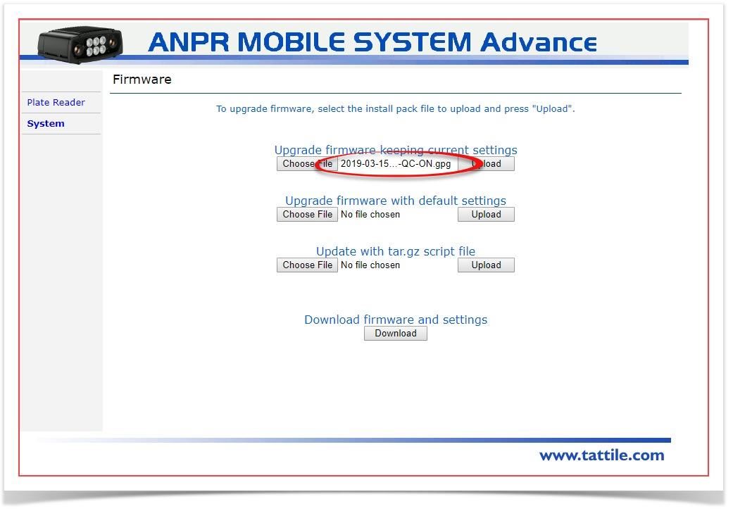
- Navigate to the location of the firmware update file to select it for upload. This will be a .gpg file.

- The file will be staged for upload. Notice the file name appears in the upgrade interface.

- Click on Upload to complete the upgrade process. This may take a little time.

Trobleshooting Tips
Powering the Camera
If the camera is not connecting to the PL8RDR there may be issues with power. Ensure that the connections are sturdy and follow the guide to Powering the Camera.
One way to check a camera to ensure it is powered on is to power up the unit and view the front of the camera using a cell phone camera. The use of the camera viewfinder does two things. It shields you from looking directly into the infrared light as well as allow you to see a slight flicker in the 6 lights on the front of the camera.
Checking Firmware updates.
You should always ensure you have the latest firmware installed.
Adjusting the Camera's View
Depending on the application of your camera, whether it be fixed or mobile, there are adjustments that can be made to improve accuracy and speed of reads.
Adjusting the angle, height and width of camera's read area can improve performance by simply defining the camera's sweet spot so to speak.