| dBm | Comment |
|---|---|
| -51 | Best |
| -80 | Minimum for best connectivity |
| -90 | Noisy connection; not stable |
| *-96* | *our office window (usable)* |
| *-107* | *LTE tablet outside (usable)* *Phone in basement* |
| -111 | Worst |
| failed | failure to get signal |
For the Survision LPR Camera configuration, go to [Survision LPR Camera Configuration](https://opscom.wiki/books/lpr-installation-manual/page/part-3-handheld-set-up)
## Connecting Wirelessly The first step is to connect to your **PL8RDR** device via wireless connection. To do so bring up your systems **Network Settings** by following the steps below Click on the **Windows Home Button** and start typing **Control Panel**. It should pop up under Best **Match** as you are typing. [](https://opscom.wiki/uploads/images/gallery/2024-06/ljlimage.png) Click on **Control Panel** to access your **Computer's Settings**. [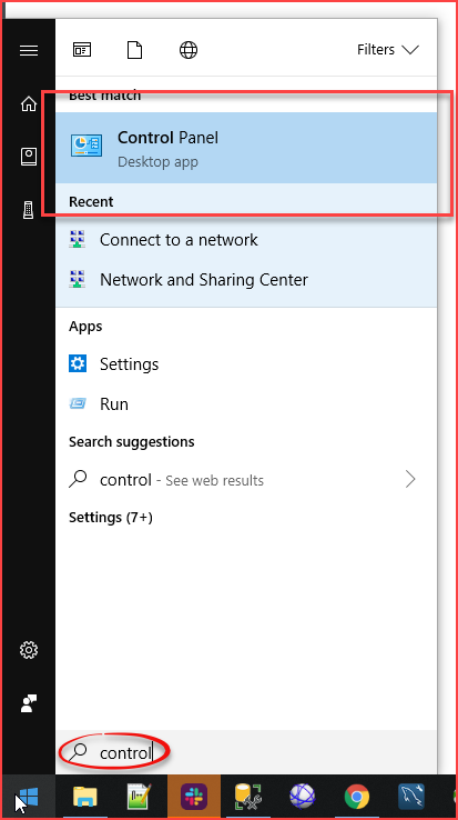](https://opscom.wiki/uploads/images/gallery/2024-06/72jimage.png) A list of all available configuration items will appear. Click on **Network and Internet.** [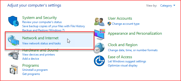](https://opscom.wiki/uploads/images/gallery/2024-06/Fn0image.png) In **Network and Sharing Center** settings click on **Connect to a Network**. [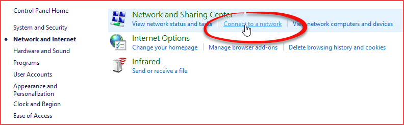](https://opscom.wiki/uploads/images/gallery/2024-06/zIjimage.png) ### Connect to pl8rdr.opscom First make sure **Wi-Fi** is turned on by clicking the network icon at the bottom right of your screen. You will see a list of networks available to you. In this case we are looking for the **pl8rdr.opscom** network. [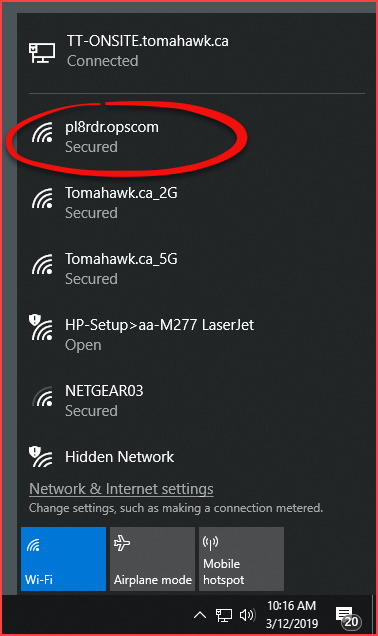](https://opscom.wiki/uploads/images/gallery/2024-06/nDzimage.png) Clicking the **pl8rdr.opsom** network will open a screen where you can click on **Connect** to join the network. You can also utilize the **Connect automatically** check box do avoid having to connect manually each time. [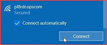](https://opscom.wiki/uploads/images/gallery/2024-06/kNtimage.png) Since the network is secured a password/PIN is required to connect. Click on **Connect using a secure key instead** to bring up a seperate password entry field. [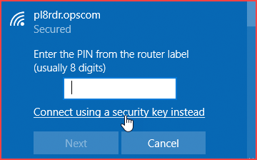](https://opscom.wiki/uploads/images/gallery/2024-06/6VNimage.png) Enter the password into the empty field and click on **Next**.**Note:** The password is provided by OPSCOM. If you do not know your password please contact
| Username | Password |
|---|---|
| superuser | superuser |
| Wired | Wireless | Port |
|---|---|---|
| 192.168.0.21 255.255.0.0 | SSID: Anpr-###### 192.168.150.1 | 1080 or 8081 |
| [](https://opscom.wiki/uploads/images/gallery/2024-06/P0Jimage.png) | [](https://opscom.wiki/uploads/images/gallery/2024-06/5cNimage.png) | [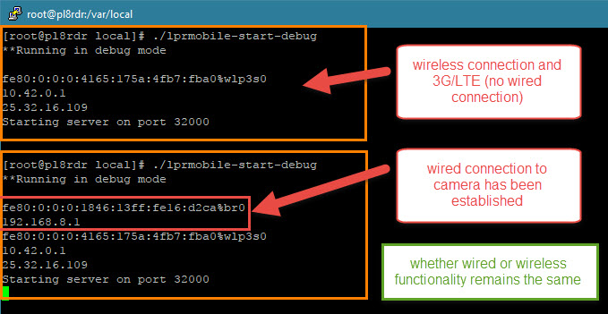](https://opscom.wiki/uploads/images/gallery/2024-06/KL9image.png) |
| [](https://opscom.wiki/uploads/images/gallery/2024-06/cgsimage.png) | [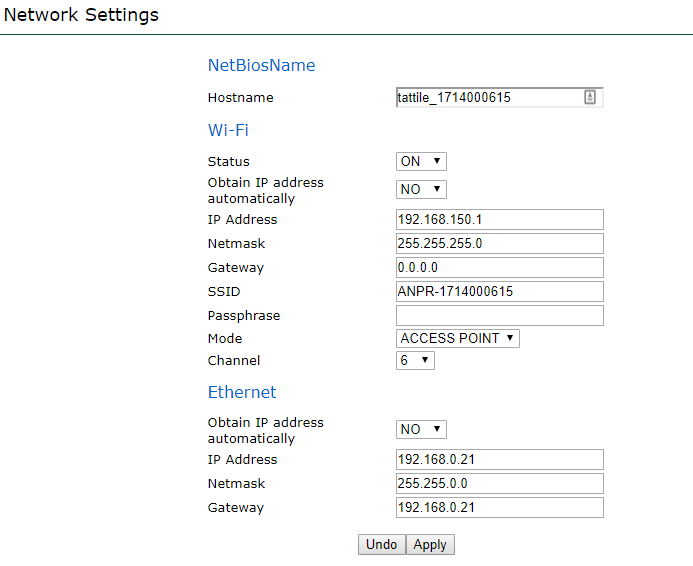](https://opscom.wiki/uploads/images/gallery/2024-06/OAvimage.png) | [](https://opscom.wiki/uploads/images/gallery/2024-06/VCKimage.png) |
| [](https://opscom.wiki/uploads/images/gallery/2024-06/RQZimage.png) | [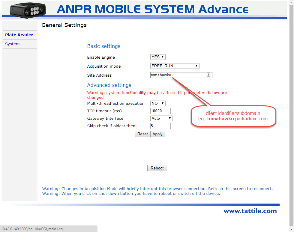](https://opscom.wiki/uploads/images/gallery/2024-06/iibimage.png) | [](https://opscom.wiki/uploads/images/gallery/2024-06/TIBimage.png) |
| [](https://opscom.wiki/uploads/images/gallery/2024-06/zvgimage.png) | [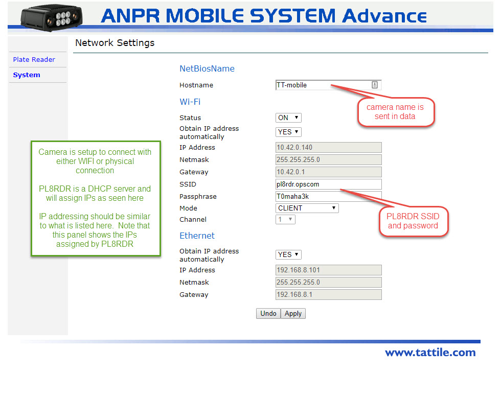](https://opscom.wiki/uploads/images/gallery/2024-06/nXiimage.png) | [](https://opscom.wiki/uploads/images/gallery/2024-06/qLnimage.png) |
**Note:** This is assuming you have a PL8RDR computer already set up. See the PL8RDR information section below for more details.
# Powering the Camera Your Survision camera should come with a cable. This is only used for providing power to the camera; the camera connects to the PL8RDR wirelessly. Power on both the PL8RDR and the Survision camera. # Connecting to a Handheld Device You will find the information for connecting to the PL8RDR [here](https://opscom.wiki/books/lpr-cameras/page/connecting-to-the-pl8rdr). # Positioning the Camera Choose a plate on a vehicle to be your reference. Park your enforcement vehicle behind it and to the side, as if you were driving past a street-parked car. The camera on your vehicle should be **5 meters** away from the reference plate, and angled **less than 30 degrees** off the front of the plate. [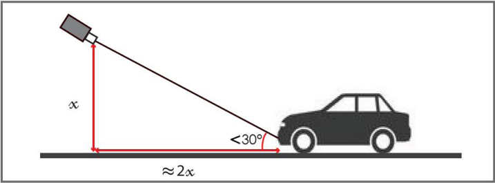](https://opscom.wiki/uploads/images/gallery/2024-06/ynbimage.png) *(This diagram shows a vertical angle, but the same applies horizontally.)* Connect to the pl8rdr.opscom Wi-Fi network on a device of your choice. The screenshots in this demonstration are from a phone, but any laptop or mobile device will work. On your tablet (or other connected device) open a web browser, enter the IP address of the camera.*For OPSCOM's test cameras, use the IPs below:* One camera: **10.42.0.11** Two cameras: **10.42.0.11** and **10.42.0.12**
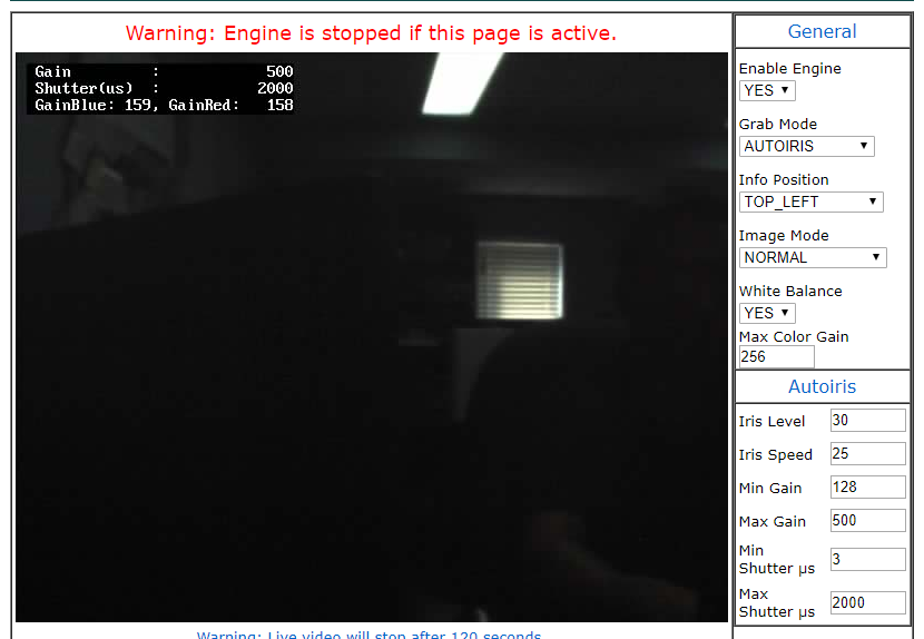
Click on "Configuration assistant". [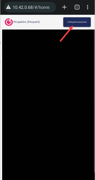](https://opscom.wiki/uploads/images/gallery/2024-06/fw0image.png) Proceed through the first 3 screens by clicking "Next" each time. These settings will have already been configured for you. [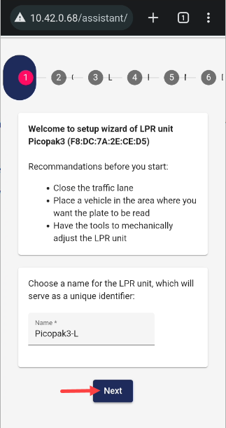](https://opscom.wiki/uploads/images/gallery/2024-06/THvimage.png) [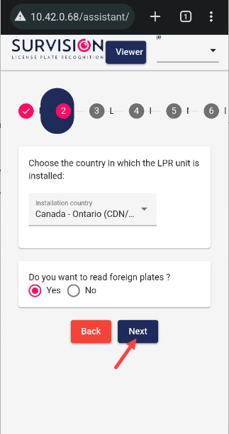](https://opscom.wiki/uploads/images/gallery/2024-06/Gx7image.png) [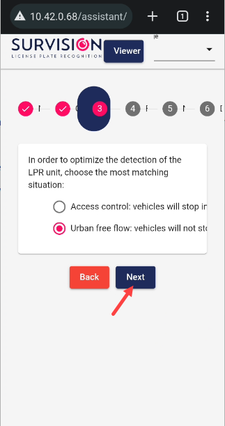](https://opscom.wiki/uploads/images/gallery/2024-06/YREimage.png) On the 4th screen, you will be prompted to set the camera angle. Adjust the camera on your vehicle until the plate you have chosen as your reference point is centered in the green box. The lines of text above the camera feed should all turn green when it is set correctly. When you are done, click "Next". [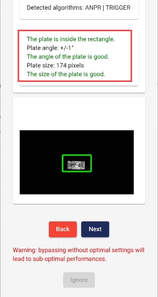](https://opscom.wiki/uploads/images/gallery/2024-06/Uloimage.png) On the 5th screen, leave all the fields blank and click "Finish". The next screen may display an error message saying no address is configured. You can safely ignore this; the address is configured on the PL8RDR. [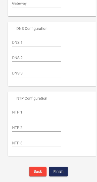](https://opscom.wiki/uploads/images/gallery/2024-06/iClimage.png) [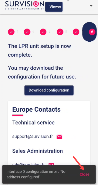](https://opscom.wiki/uploads/images/gallery/2024-06/XyQimage.png) Your camera should now be set up at the correct angle. You can go through this quick setup process every time you need to reposition the camera on your vehicle. # Static Camera Setup ## Adding a Camera In order to activate your LPR access, and if equipped, information feed for Make, Model Color (MMC) information, you must access your system configuration and change two settings, as follows; 1. Go to **System Configuration** and click on **System Settings**. 2. Select the **License Plate Recognition** tab. There will be two checkboxes to enable, one is called **Using Mobile LPR.** The other is called **Enable MMC.**The setting that is labeled as **MMC** is only going to work if you have a camera that supports **MAKE, MODEL, COLOR information collection.** If so, **enable the checkbox** for this setting as well. Other wise, this information will be discarded even if your camera does collect it.
To begin go to the Violations menu and click on LPR and Chalking. Then click on Camera Setup. [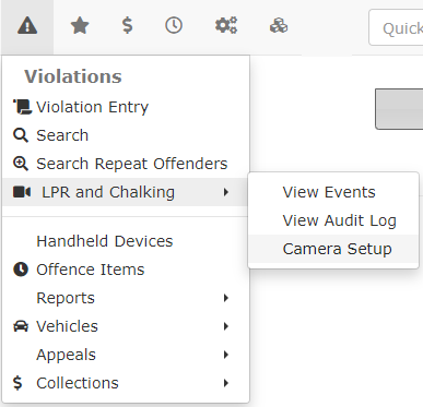](https://opscom.wiki/uploads/images/gallery/2024-06/GCiimage.png) The LPR Camera Configuration Page displays. [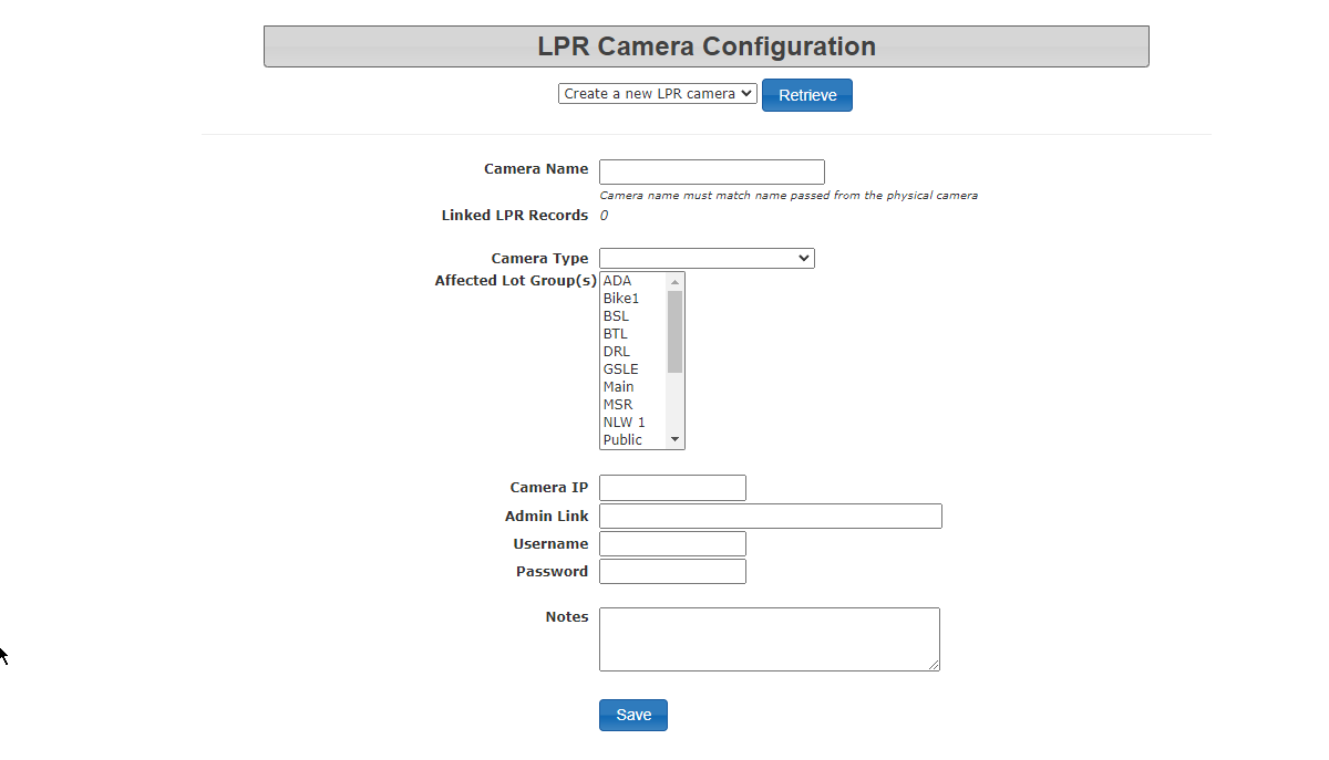](https://opscom.wiki/uploads/images/gallery/2024-06/tlDimage.png) Fill in the form with the required information: - Camera Name - Camera Type (entrance, exit or tracking) - Camera IP You may also want to record the following optional information: - Admin link (to access camera configuration - Username - Password - Notes Click save to complete the process. [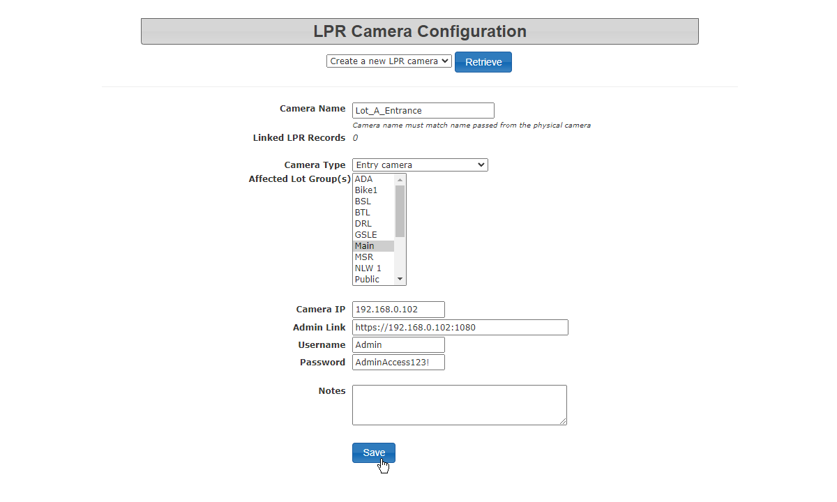](https://opscom.wiki/uploads/images/gallery/2024-06/uTRimage.png) Once the camera is configured you are able to look up or edit the information from this interface as well. [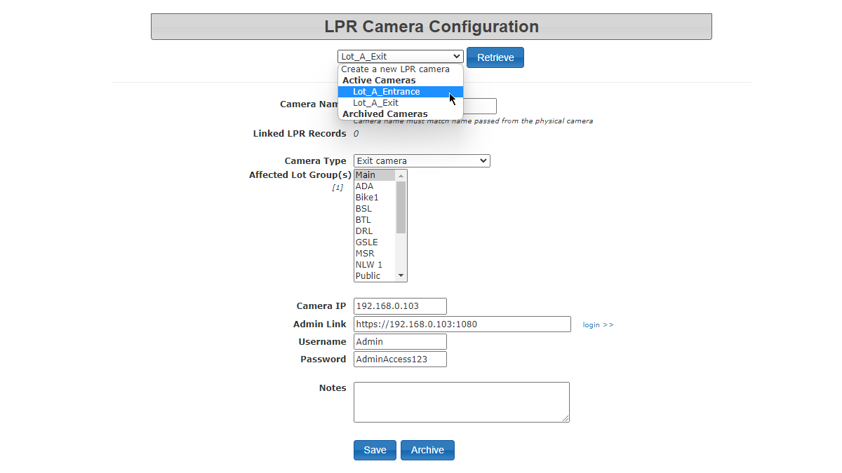](https://opscom.wiki/uploads/images/gallery/2024-06/H60image.png) Clicking on this link will bring you to the actual camera where you log in using the displayed credentials in order to configure or adjust settings on the camera itself. [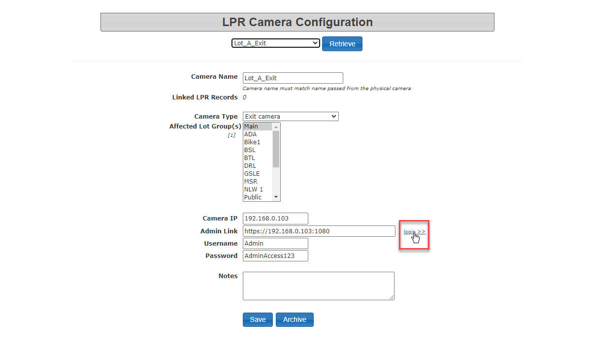](https://opscom.wiki/uploads/images/gallery/2024-06/nleimage.png) When complete LPR Events can be set to display data from the specific camera selected. # LPR Plate Lookups and Fuzzy Filtering ## Background The OperationsCommander system has the ability for the system to map plates to new values. In layman's terms this means that this process of filtration can take an image of a plate and find many possibilities of what the plate may be matched to based on commonly misconstrued characters and the license plates registered or in the known area database. An example of this may be a plate that is read by LPR may be read as **ABC128** when the plate is actually **ABC123** . The user is able to make this update and store the details. This can be problematic for the user if the plate is never seen again and **8** 's are regularly interpreted as **3** 's ## Update This issue in the functionality of the LPR software is addressed by the use of the above methods and the use of the lookup table implemented to match which characters are easily misconstrued. The sample lookup table that follows is comprised of data from past LPR updates by users;| **Character** | **Similar Characters** | **Character** | **Similar Characters** | |
| **1** | ``` "1I" ``` | **K** | ``` "HKR" ``` | |
| **2** | ``` "2Z" ``` | **M** | ``` "HKM" ``` | |
| **3** | ``` "38B" ``` | **O** | ``` "0DOQ" ``` | |
| **5** | ``` "5S" ``` | **P** | ``` "FP" ``` | |
| **8** | "38B" | **Q** | ``` "0DOQ" ``` | |
| **B** | ``` "38B" ``` | **R** | ``` "HKR" ``` | |
| **D** | ``` "0DOQ" ``` | **T** | ``` "TY" ``` | |
| **E** | ``` "EF" ``` | **V** | ``` "VY" ``` | |
| **F** | ``` "EFP" ``` | **Y** | ``` "VTY" ``` | |
| **H** | ``` "HKMR" ``` | **Z** | ``` "2Z" ``` | |
| **I** | ``` "1I" ``` |
The Static Camera Chalking feature provides OPSCOM administrators and enforcement officers with a digital record of vehicles entering and exiting monitored lots. This information acts like a 24 x 7 Patrol Officer and serves as proof during disputes or appeals, as the time-stamped image is acceptable in a court of law if the date/time stamp is clear.
If your camera hardware supports it, a static camera chalk includes the chalk image associated with the vehicle entry, which shows both the license plate and the entire car with a visible date/time stamp. This creates a digital trail that replaces manual tire marking. When reviewing past chalks, you can see a map location of where the vehicle was chalked, a date and time stamp for the chalk event, and an image taken at the time (accessible via a camera icon). There may also be comments added by the officer at the time of chalking, and a distance reading indicating the distance from the first chalk record to the present position. [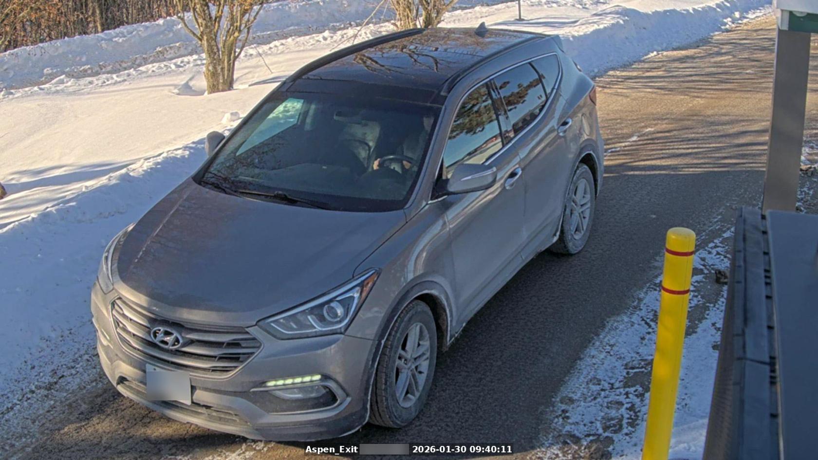](https://opscom.wiki/uploads/images/gallery/2026-03/chalk-example-with-static-cameras.jpg) ### Best Practices and Considerations - **Audit Camera Accuracy:** Regularly check that the camera is pointed correctly and that the images are clearly showing the vehicle in frame. - **Dispute Resolution:** When handling an appeal, always provide the **Chalk Image** as it shows both the plate and the vehicle context, which is typically acceptable in a court of law.