If you have purchased a complete kit for Mobile LPR, you will find the following equipment in the box. You will also receive a detailed packing list with your shipment. Please unpack it carefully and ensure you have everything.
- 1x Android tablet; sent in factory box; charger will be in the box. - 1x Bluetooth printer sent in the factory box, this typically includes a charger and 1 roll of blank paper - 1x Survision Picopak LPR camera - 1x Installer pack with all connectors and power cables. This includes a DC 12 V car adapter and a cable splitter - 1x PL8RDR computer; sent in factory box. This typically includes: - Power adapter (AC to DC 12 V; 5.5 mm x 2.5 mm barrel connector male end) - 2x Wi-Fi antennas - 2x 4G LTE antennas (T-bar) - Mounting equipment - 1x SIM card; inserted into the PL8RDR # Part 1: Getting an Installer & Cable Modifications (Optional) First things first, find an installer to setup all the cabling you need in your vehicle to power the cameras and the PL8RDR. Verify with your installer how you want your setup to function. They will be able to decide how your new equipment gets powered and how everything gets cabled.**Please note:** Your installer may have to modify the provided cables. The Survision Camera cable has a car adapter which could need to be cut off, and the 12V 5.5x2.5 Male-Female Power Plug put in its place.
#### Survision Camera Cable - Your installer may need to refer to the pin/cable specification document available here: [PICOPAK3 PINOUT & CONNECTIONS\_English.pdf](https://opscom.wiki/attachments/3) - If you have the Survision cable and the **M12 Y-Splitter** shown below, please ensure these are the connections:| [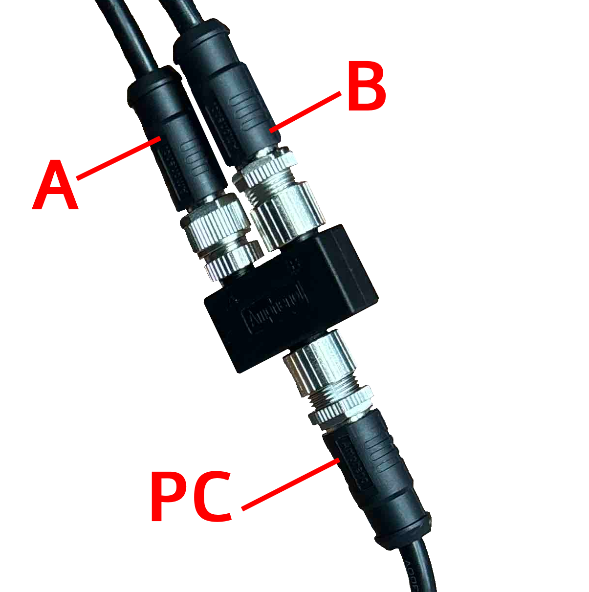](https://opscom.wiki/uploads/images/gallery/2026-05/8q4camera-connection-diagram.png) | ##### ##### Cable Configuration: **A -** Power Input **B -** LPR Camera **PC -** Direct to PL8RDR |
| [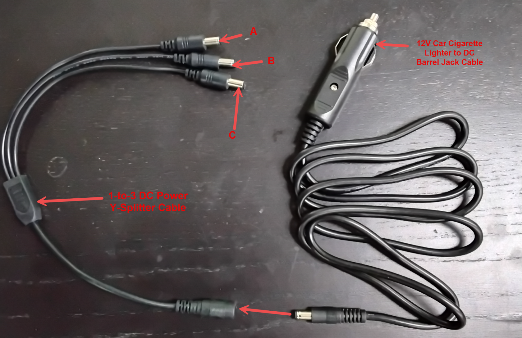](https://opscom.wiki/uploads/images/gallery/2026-05/image.png) | Cable Configuration: **A -** LPR Camera 1 **B -** LPR Camera 2 **C -** PL8RDR **12V Car Cigarette Lighter Jack -** Connector Vehicle 12V auxiliary power outlet |
Let's connect all the gear. A typical OPSCOM LPR system includes a Survision LPR camera, a PL8RDR device, a 4G/LTE tablet, a Bluetooth printer, and a vehicle mount.
##### The PL8RDR - (LPR Computer) This is the brains of the operation and is a small micro-computer that is normally stored in the vehicles truck. [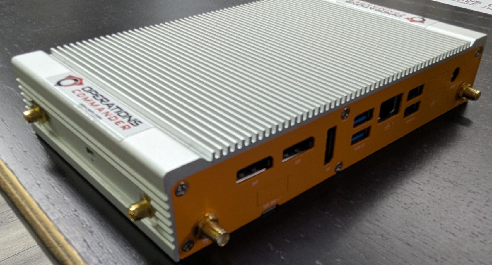](https://opscom.wiki/uploads/images/gallery/2025-08/pxl-20250730-181653253.jpg) ##### Powering the PL8RDR There are two options for powering the PL8RDR. The PL8RDR computer can be powered using a vehicle power adapter or a wall plug. The setup steps are the same for both options. The PL8RDR uses a **12V DC power source** and should be connected with an inline fuse. ##### **Option #1:** Using the Vehicle Power Adapter For a single Camera setup [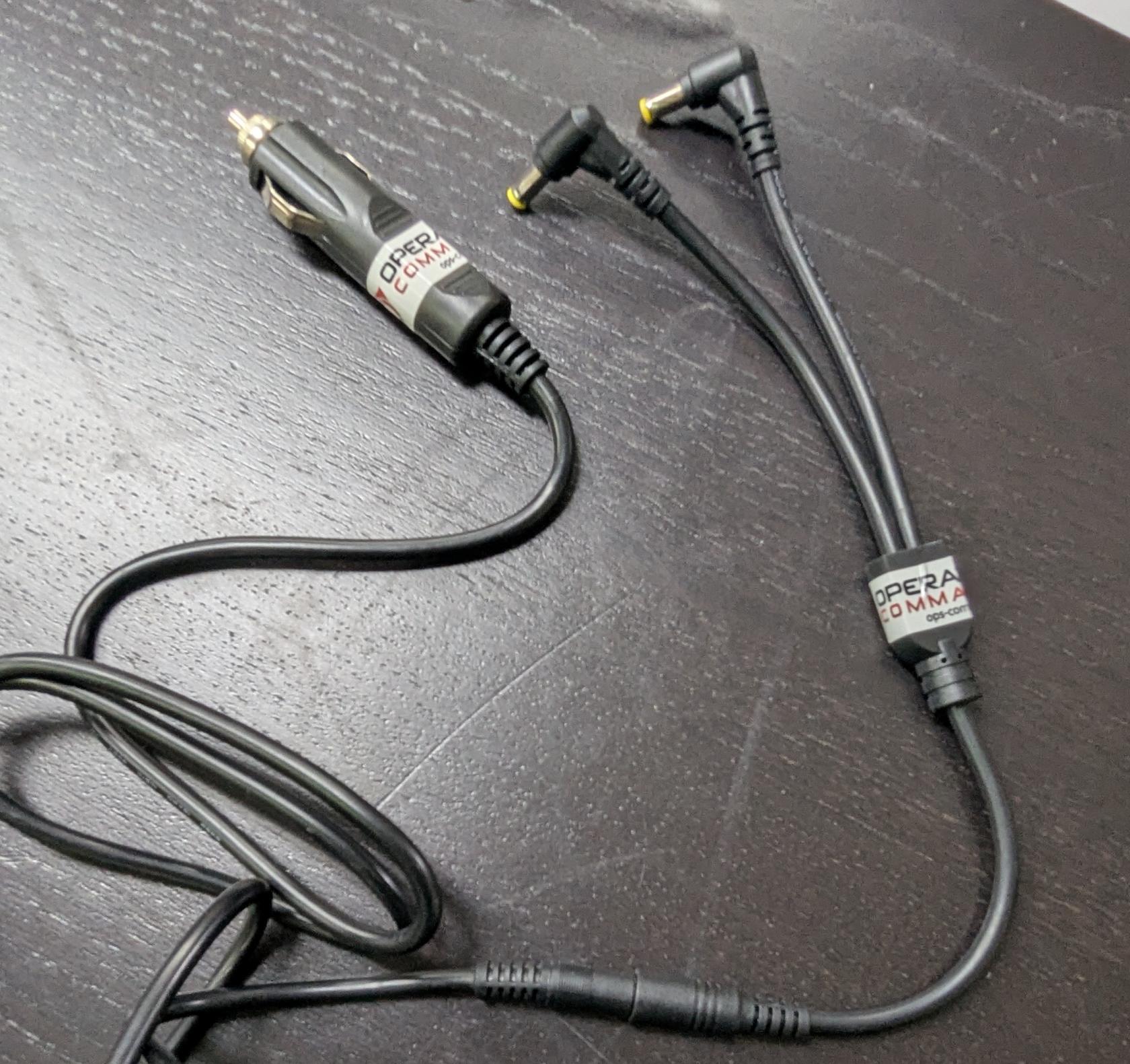](https://opscom.wiki/uploads/images/gallery/2025-08/pxl-20250730-181745814.jpg) For a 2-Camera setup [](https://opscom.wiki/uploads/images/gallery/2026-05/zB9image.png) - **Option #2:** Using a wall plug. [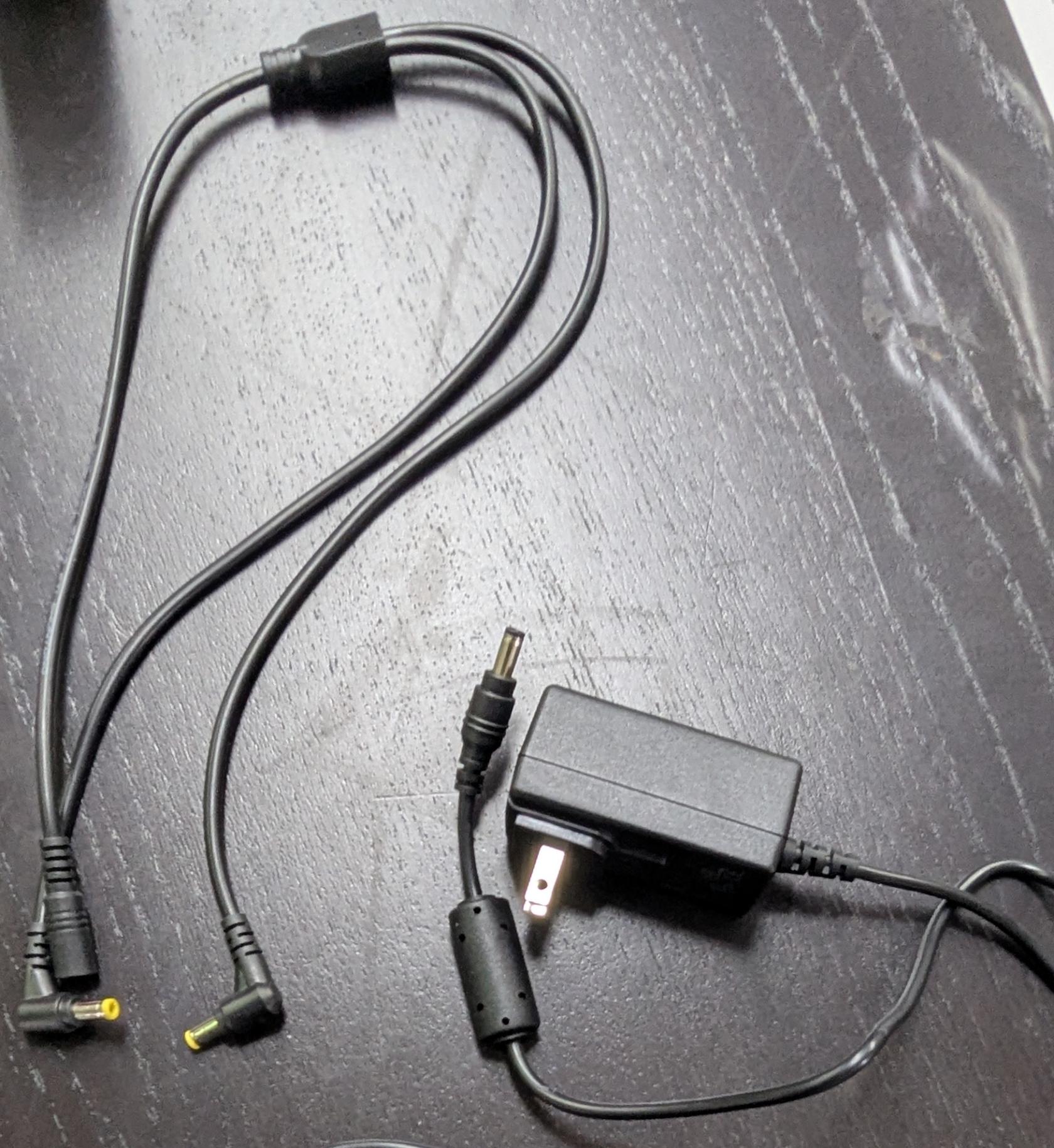](https://opscom.wiki/uploads/images/gallery/2025-08/pxl-20250730-182123734.jpg)In this guide and pictured below, we are using *Option #2: Using a wall plug.* If you are setting this up in a vehicle, follow the exact same set-up steps but use the vehicle plug power adapter instead. The rest of the connections remain the same.
### Step-by-Step #### The Wall Power Cord - Connect the splitter to the rest of the power cord, as shown below: [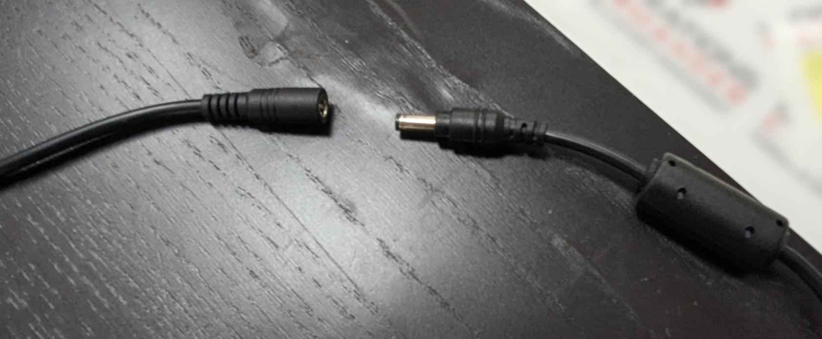](https://opscom.wiki/uploads/images/gallery/2025-08/pxl-20250730-182154868.jpg) [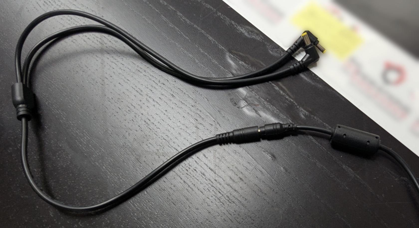](https://opscom.wiki/uploads/images/gallery/2025-08/pxl-20250730-182208515.jpg) - Plug in the other side to the wall socket or the vehicle power adapter, depending on your setup. - Next, get these 3 items ready: - LPR power/data cord - Camera - PL8RDR computer [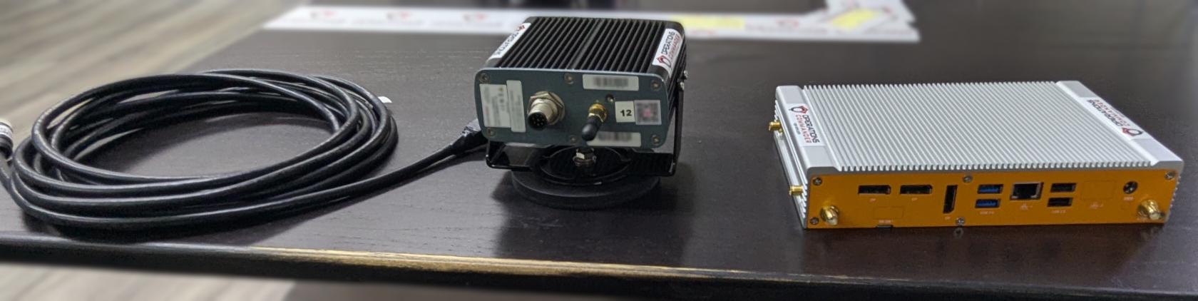](https://opscom.wiki/uploads/images/gallery/2025-08/pxl-20250730-182446172.jpg)Notice the two different ends on the LPR power/data cord. Pictured below:
[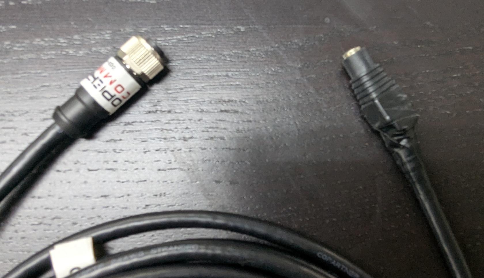](https://opscom.wiki/uploads/images/gallery/2025-08/pxl-20250730-182612558.jpg)The cable shown above may vary depending on your setup. This version includes a female barrel plug connector.
- Connect one of the power cords to the LPR data/power cord, as shown below: [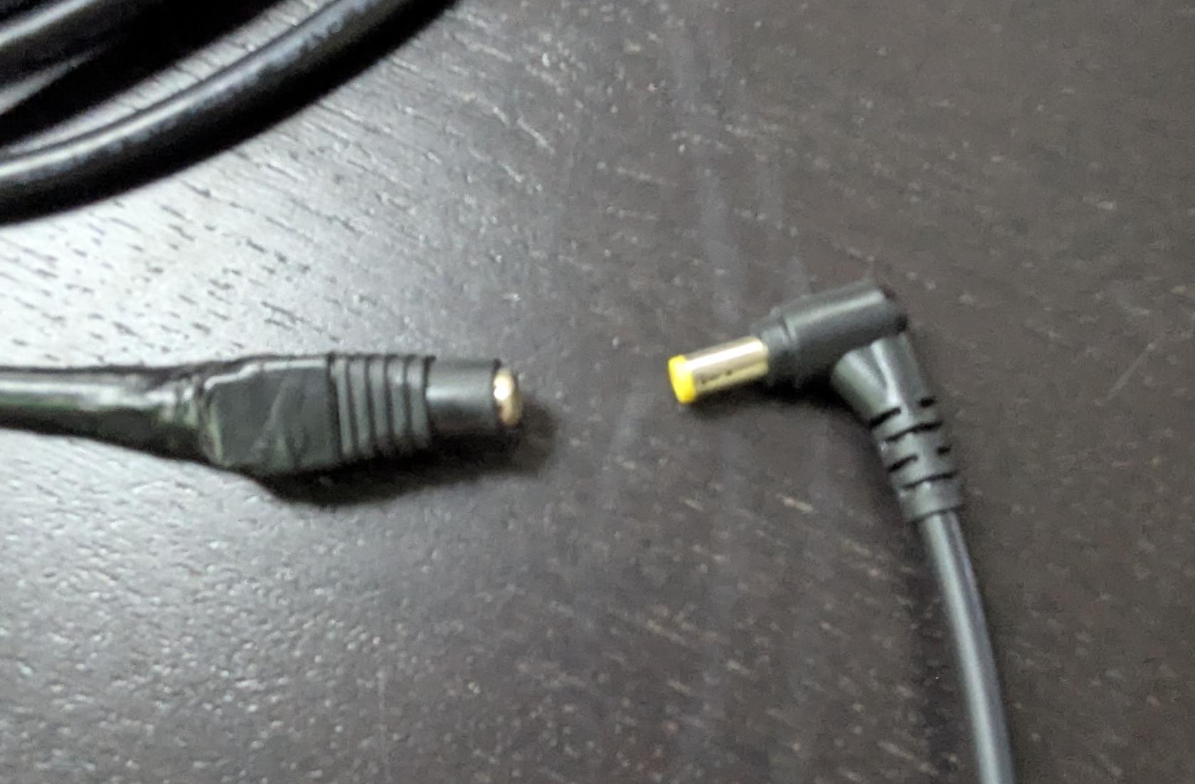](https://opscom.wiki/uploads/images/gallery/2025-08/pxl-20250730-182629557.jpg) - Align pins and attach the cord to the camera, as shown below: [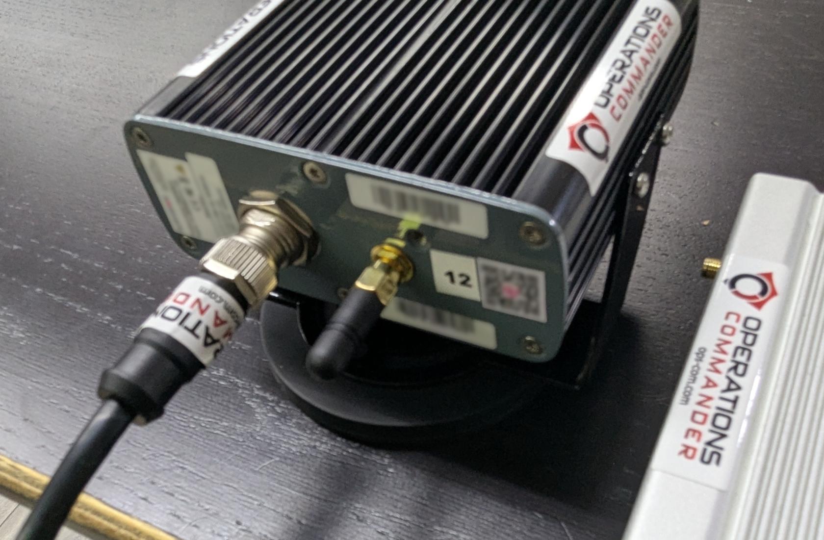](https://opscom.wiki/uploads/images/gallery/2025-08/pxl-20250730-182722145.jpg) - Plug in the other power source into the PL8RDR. Your setup should look like the picture below: [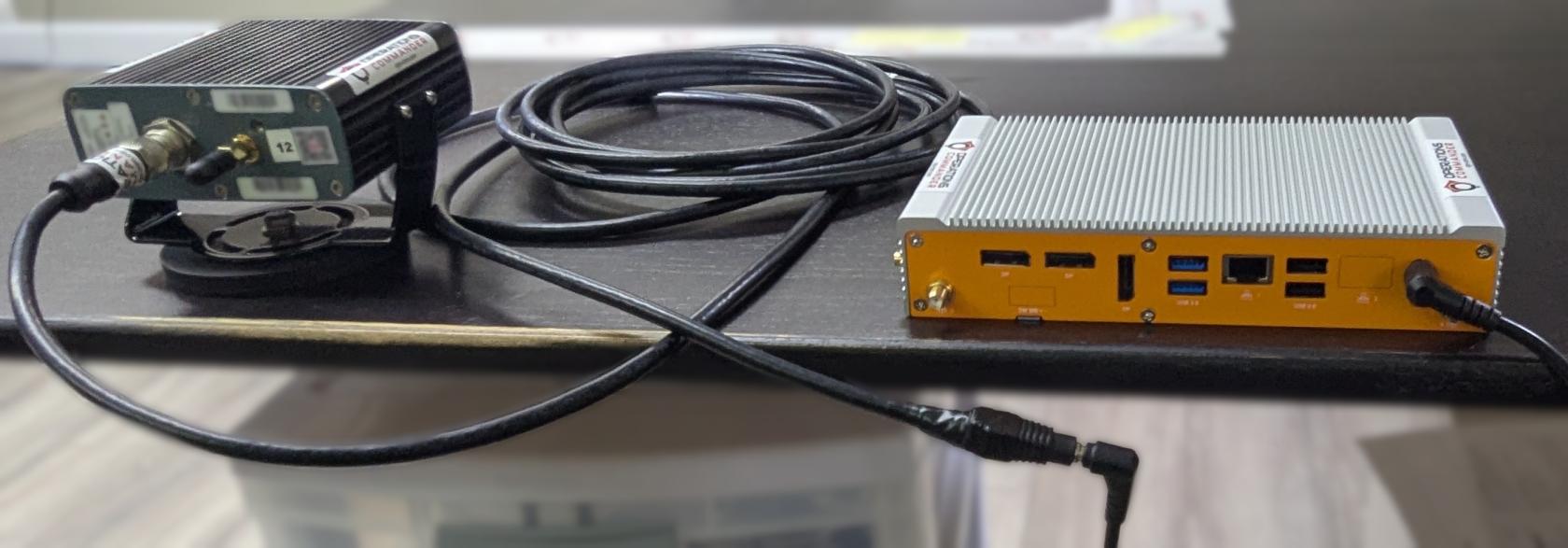](https://opscom.wiki/uploads/images/gallery/2025-08/pxl-20250730-182948033.jpg) - Or the picture below if you have 2 LPR camerasYou will know that you have succeeded once you see the camera emit a strong light.
Now you'll need to attach the antennas to the PL8RDR. This establishes a connection to the OPSCOM servers.All antennas need to be attached as shown or the device will not function as intended.
Here are the 3 antennas that you will need, as pictured below: - 2 x LAN Antennas - 1 x OPSCOM Wireless Connection Antenna [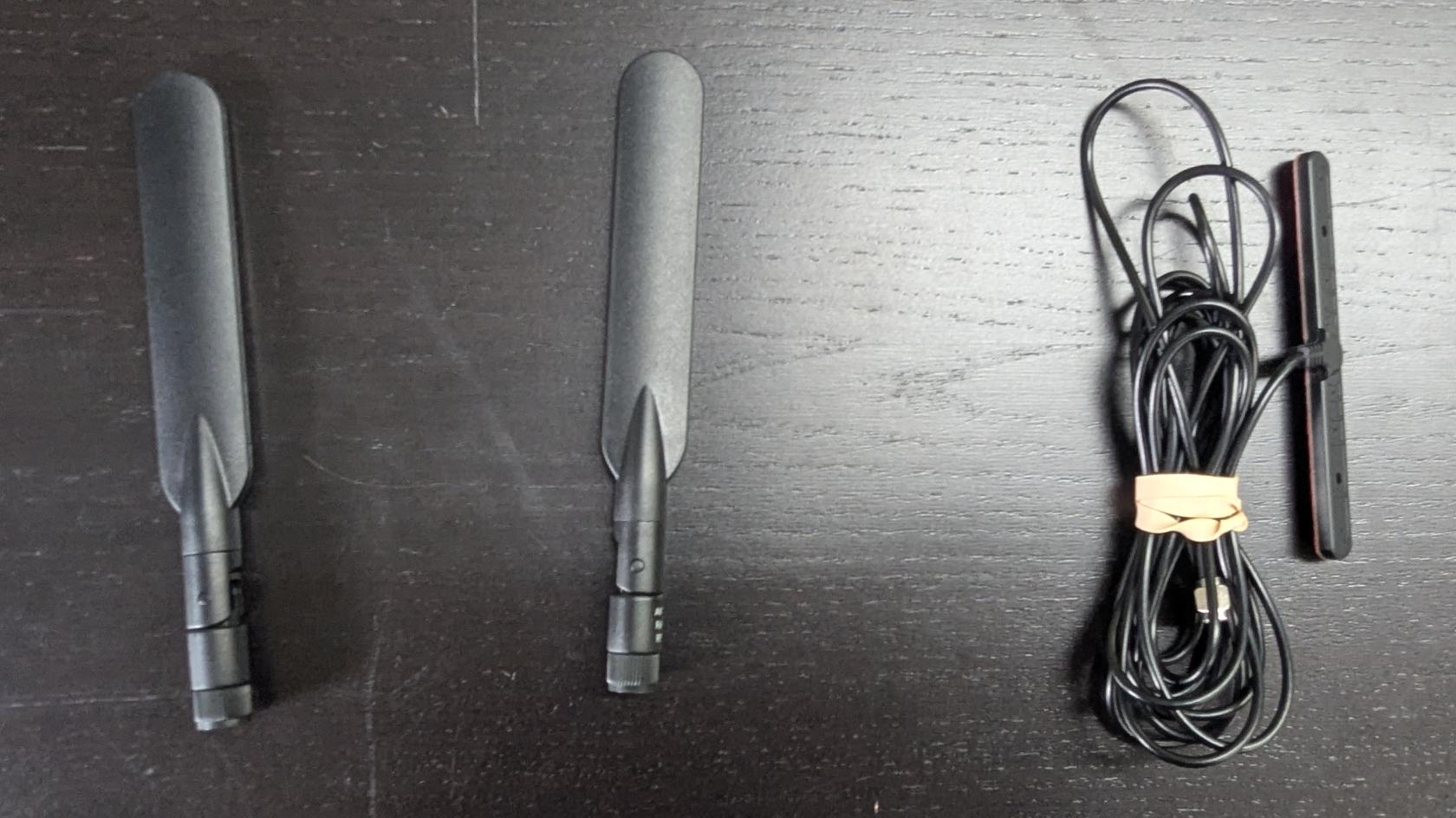](https://opscom.wiki/uploads/images/gallery/2025-08/pxl-20250730-183059617.jpg)An extra Wireless Connection Antenna (T-Bar) may be included. It may be used if you experience connectivity issues. Otherwise, it isn't required at this time.
- Attach the cable antennas to the port on the back left of the PL8RDR, as shown below: [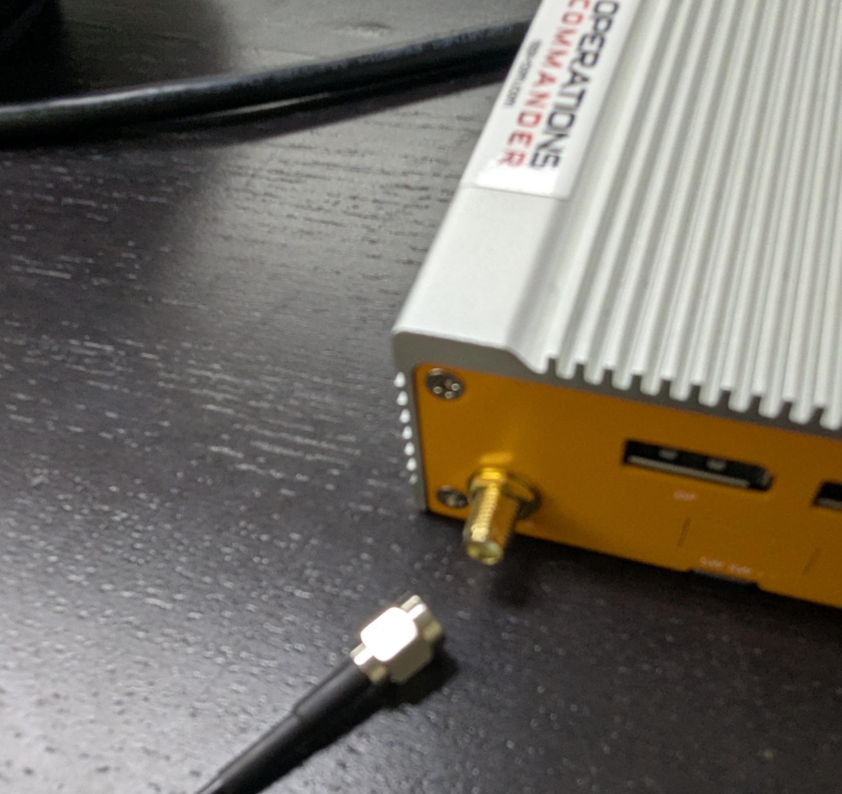](https://opscom.wiki/uploads/images/gallery/2025-08/pxl-20250730-183236060.jpg) - Lightly screw in the antennas on the side of the PL8RDR, as shown below. [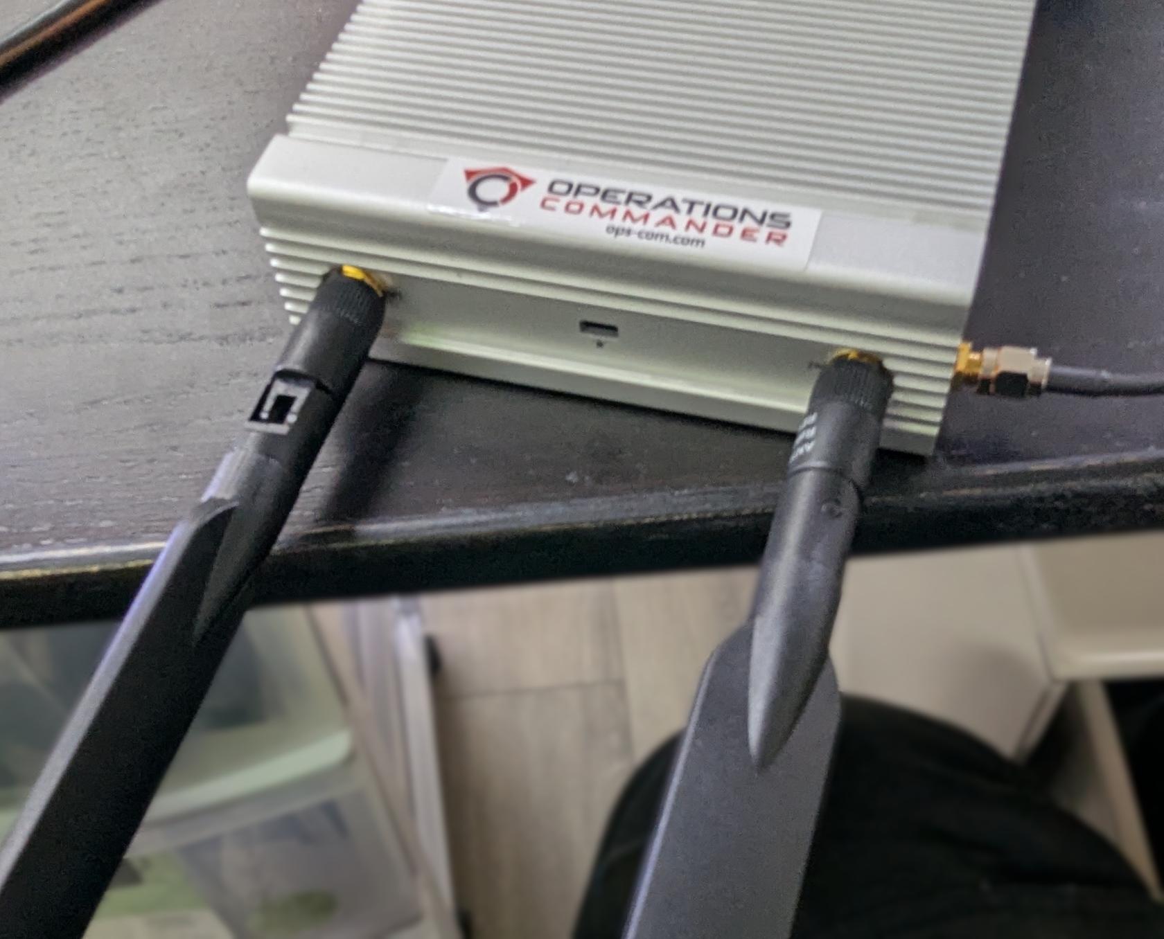](https://opscom.wiki/uploads/images/gallery/2025-08/pxl-20250730-183623099.jpg) - Make sure that the hinge is facing in the correct direction, as shown below, and gently fold the antennas into the upright position. [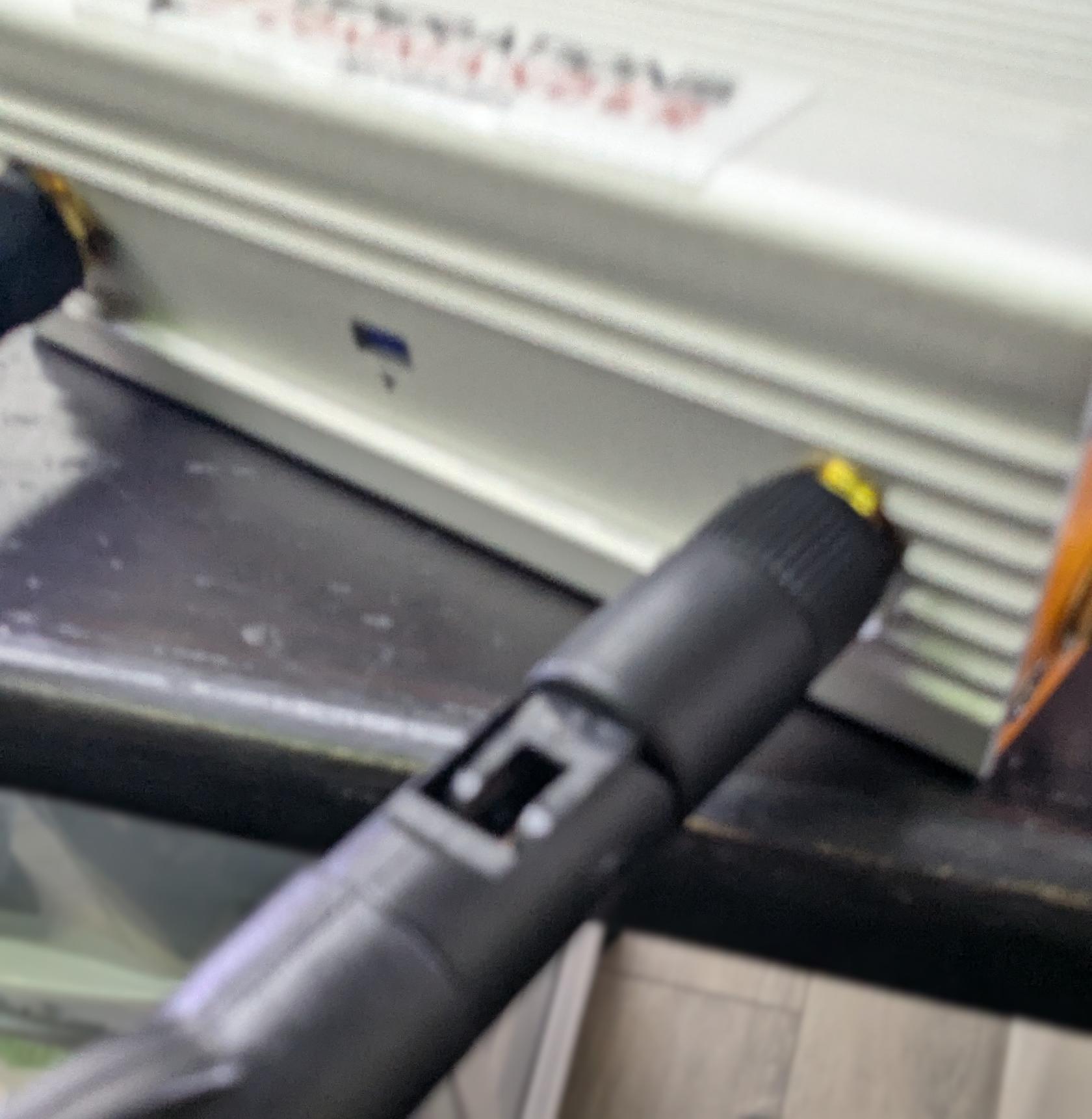](https://opscom.wiki/uploads/images/gallery/2025-08/pxl-20250730-183632241.jpg) - Make sure to place the corded antennas in an elevated location with a good data signal to ensure proper connectivity. This is what you should have when you’re done: Single camera setup [ 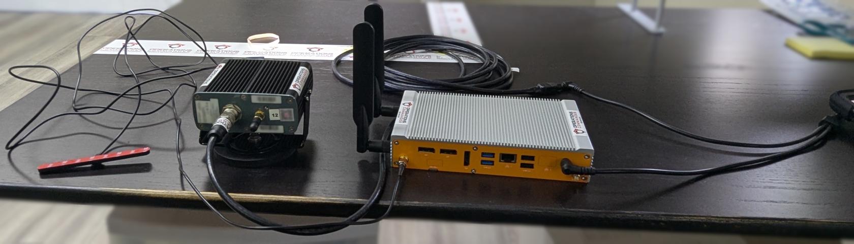](https://opscom.wiki/uploads/images/gallery/2025-08/JRfpxl-20250730-183742139.jpg) 2 Camera setup [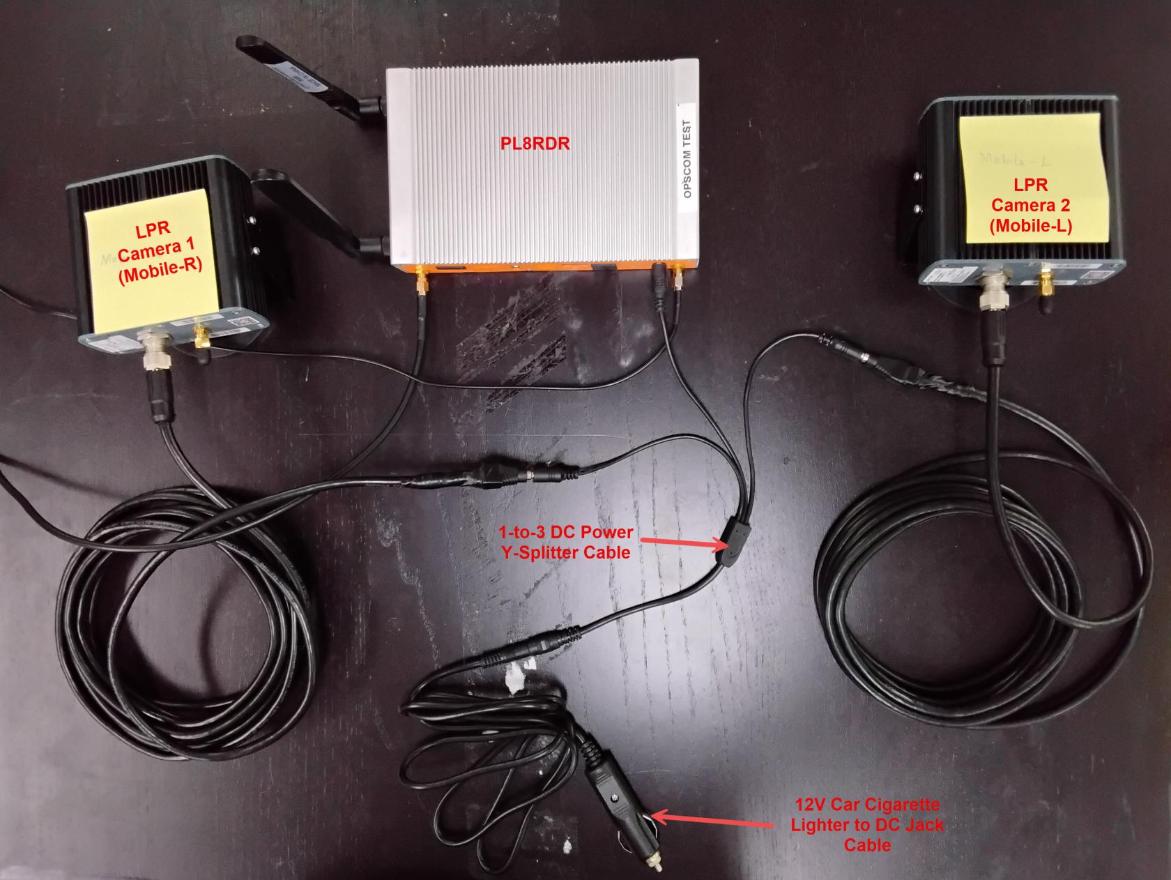](https://opscom.wiki/uploads/images/gallery/2026-05/TFT20260501-113731.jpg) ### [Positioning the Survision Camera](https://opscom.wiki/books/lpr-cameras-setup-playbook/page/setting-up-your-survision-lpr-camera) Proper camera positioning is critical for accurate license plate reads. Follow these steps to get it just right: - **Find Your Reference:** Choose a vehicle with a license plate to use as your reference point. - **Position Your Vehicle:** Park your enforcement vehicle behind and to the side of the reference car, as if you were driving past it on the street. - **Camera Placement:** The camera on your vehicle should be between 3 & 8 meters away from the reference plate. It should also be angled **less than 30 degrees** off the plates you are scanning. [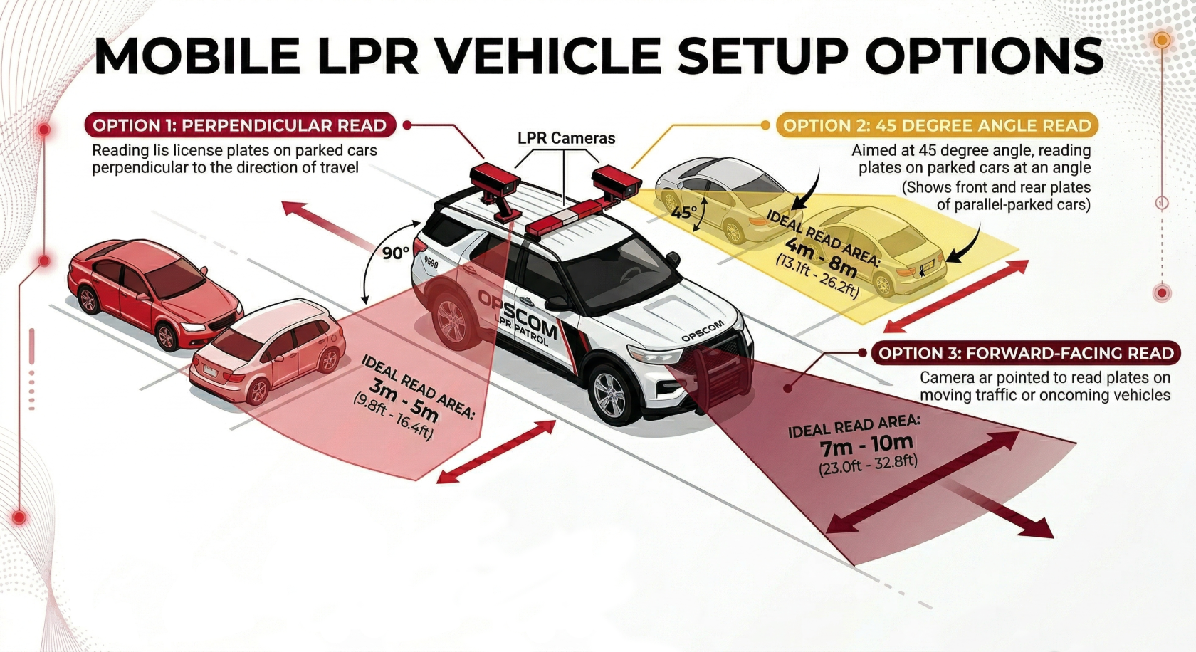](https://opscom.wiki/uploads/images/gallery/2026-03/mobile-lpr-camera-setup-options.png) - **Use the Configuration Assistant:** On a device connected to the `pl8rdr.opscom` Wi-Fi network, open a web browser and enter the camera’s IP address. Click on "Configuration assistant". - **Set the Camera Angle:** Follow the prompts by clicking "Next" through the first three screens. On the fourth screen, you will be asked to set the camera angle. Adjust the camera on your vehicle until the reference plate is centered in the green box on your screen. The lines of text above the camera feed should all turn green when it is correctly positioned. - **Finish Setup:** Click "Next" when you're done. On the final screen, leave the fields blank and click "Finish". You may see an error message, but you can safely ignore it, as the address is configured on the PL8RDR. # Part 3: Handheld Set-UpIf you’re using your own tablet, please follow the instructions directly below. If you purchased a tablet from us, skip to Next Steps.
- The camera needs to be configured for 10.42.0.11, which it should already be. - Next, you’ll need to enter that IP address in the panel under the camera IP settings. - The handheld connects directly to the camera at that IP to establish the link and transfer data. This is different from the PL8RDR, which the handheld uses to communicate with external systems. Here is where you will need to enter the camera IP: [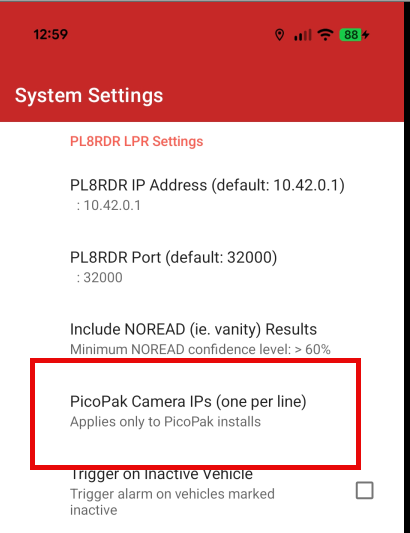](https://opscom.wiki/uploads/images/gallery/2025-11/image.png) --- ### Next StepsOnce your hardware is set up, you'll use the OPSCOM Parking Enforcement app on a handheld device. The app has already been installed on your handheld device and the printer has also been paired. If your printer wasn't purchased through us, [refer to this wiki article](https://opscom.wiki/books/legacy-android-enforcement-app-OPSCOM-parking-enforcement/page/choosing-and-configuring-printers).
- **Connecting to the PL8RDR Network:** The PL8RDR broadcasts a Wi-Fi network named `pl8rdr.opscom`. You'll need to connect your device to this network to scan plates. The password for the network is `T0maha3k`. - **App Login:** Select the OPSCOM Parking Enforcement app on your device and log in using your OPSCOM admin username and password. You are ready to test it out! - **Searching for Vehicles:** You can search for vehicles using three methods: typing the plate number, using voice command, or using the LPR camera with OCR technology. - **E-Chalking (Virtual Chalking):** This feature electronically tracks how long a vehicle has been parked. It creates a time-stamped image of the license plate and the entire car, which can be attached to a violation. The chalked image is saved with the violation unless you delete it. - **Issuing Violations:** You can issue violations to a person or a vehicle. The system will perform a secondary check and issue a warning if a plate has a valid permit, but it will still allow you to proceed with the violation at your discretion. If you have any issues refer to the [troubleshooting guide](https://opscom.wiki/books/lpr-installation-manual/page/troubleshooting-tips) on this page!