


| Tablet (Handheld) |
| PL8RDR Computer |
| SurVision Picopak Camera |
| LAN Antennas |
| OPSCOM Wireless Connection Antennas |
| LPR Power/Data Cord |
| Mobile Printer |
| Wall Power Cord |
| Vehicle Power Cord |
| Printer Power Cord |
In this guide and pictured below, we are using *Option #2: Using a wall plug.* If you are setting this up in a vehicle, follow the exact same set-up steps but use the vehicle plug power adapter instead. The rest of the connections remain the same.
This is what you should have when you’re done: [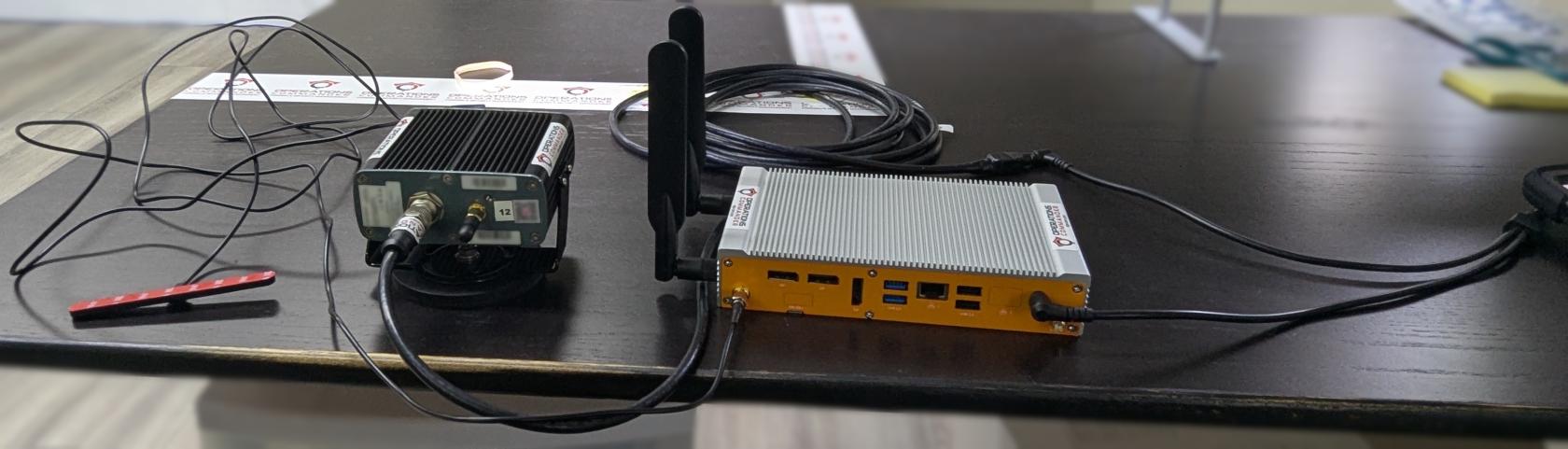](https://opscom.wiki/uploads/images/gallery/2025-08/JRfpxl-20250730-183742139.jpg) --- ### Step-by-Step #### The Wall Power Cord - Connect the splitter to the rest of the power cord, as shown below: [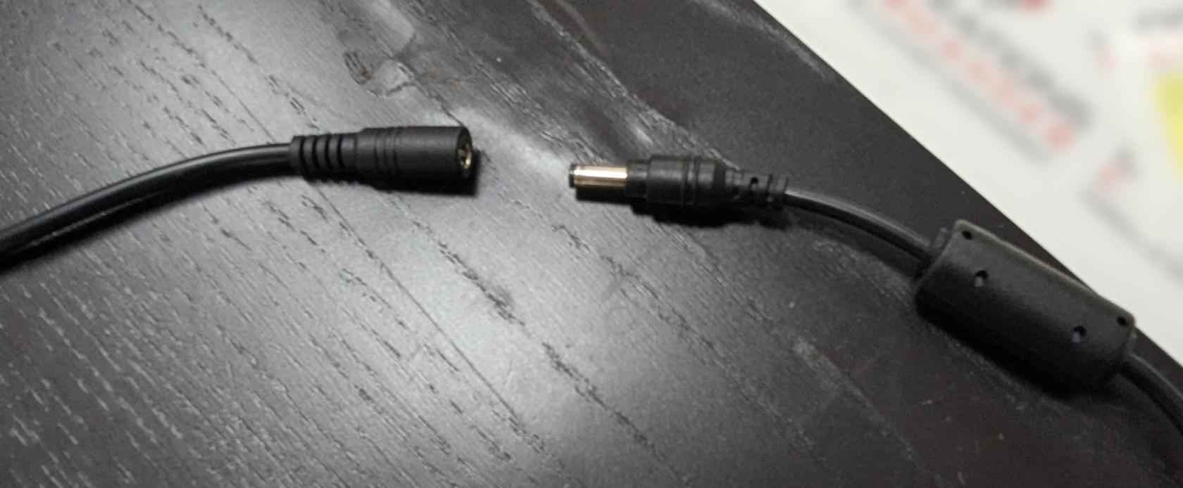](https://opscom.wiki/uploads/images/gallery/2025-08/pxl-20250730-182154868.jpg) [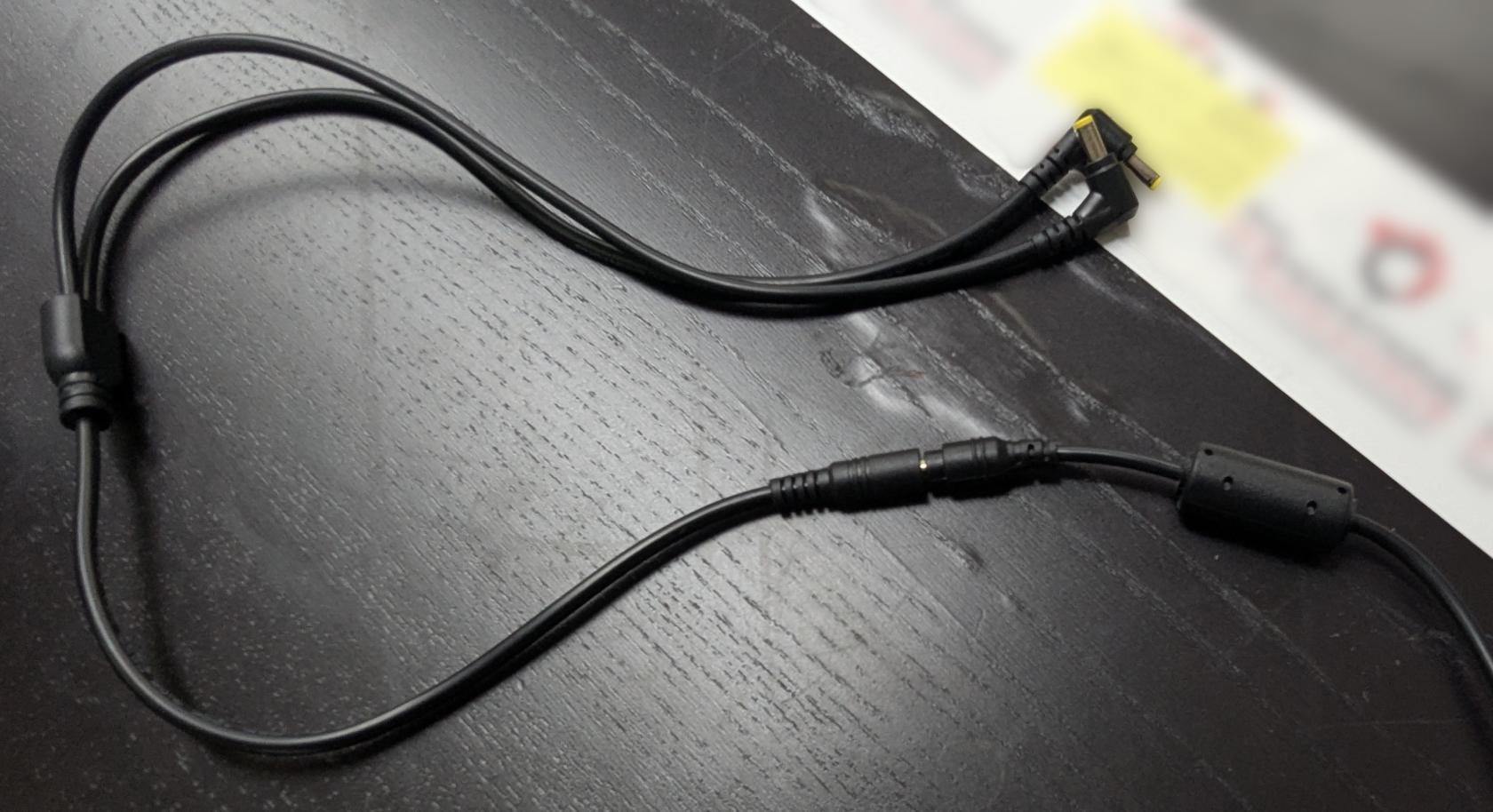](https://opscom.wiki/uploads/images/gallery/2025-08/pxl-20250730-182208515.jpg) - Plug in the other side to the wall socket or the vehicle power adapter, depending on your setup. Next, get these 3 items ready: 1. LPR power/data cord 2. camera 3. PL8RDR computer [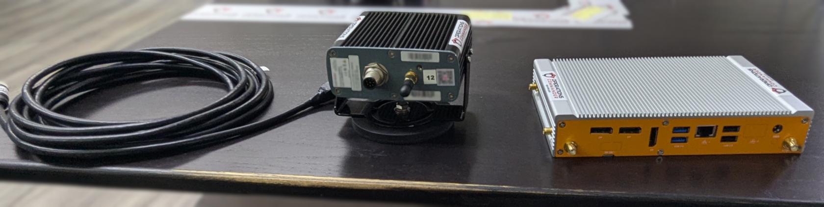](https://opscom.wiki/uploads/images/gallery/2025-08/pxl-20250730-182446172.jpg)Notice the two different ends on the LPR power/data cord. Pictured below:
[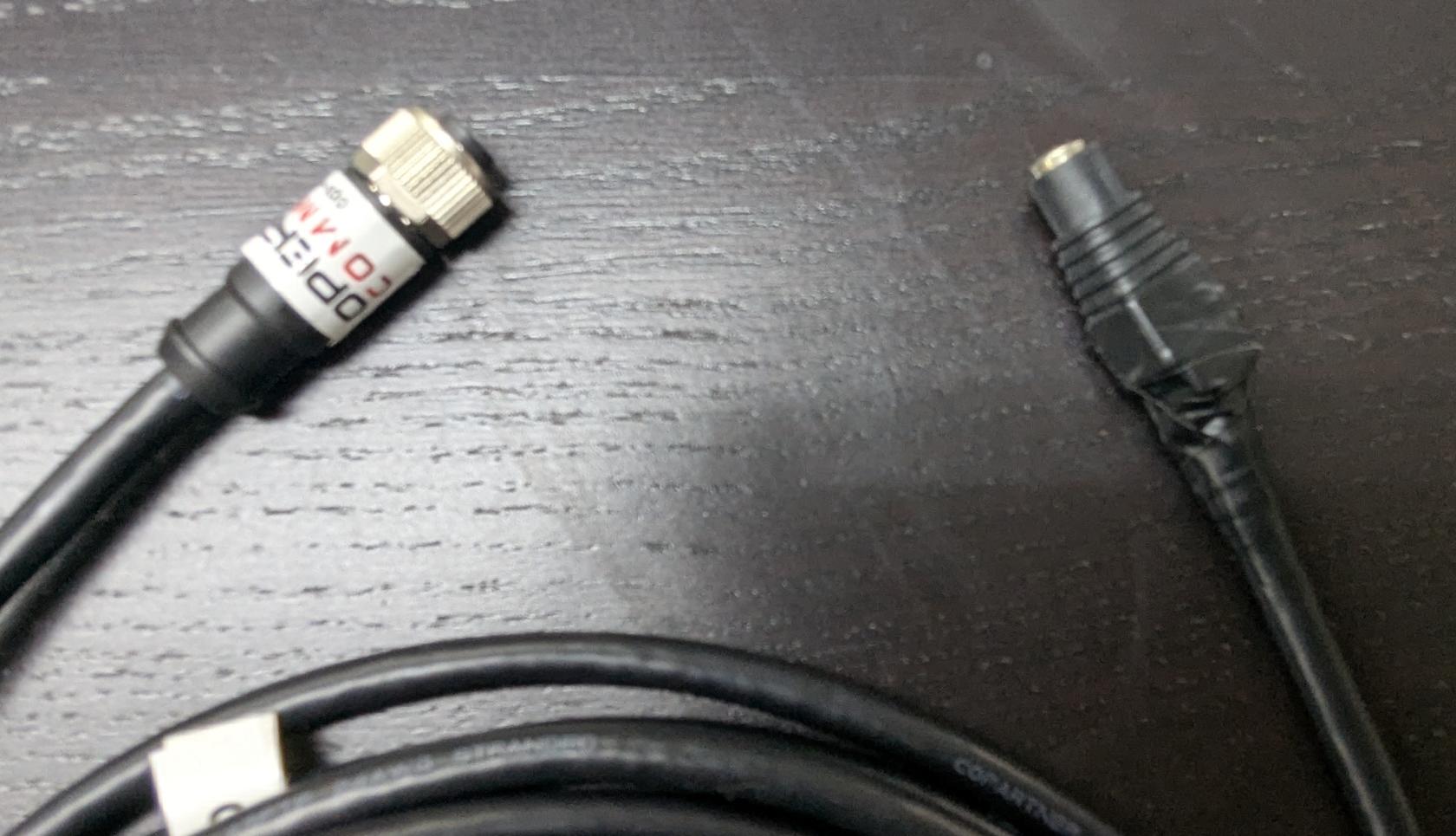](https://opscom.wiki/uploads/images/gallery/2025-08/pxl-20250730-182612558.jpg) - Connect one of the power cords to the LPR data/power cord, as shown below: [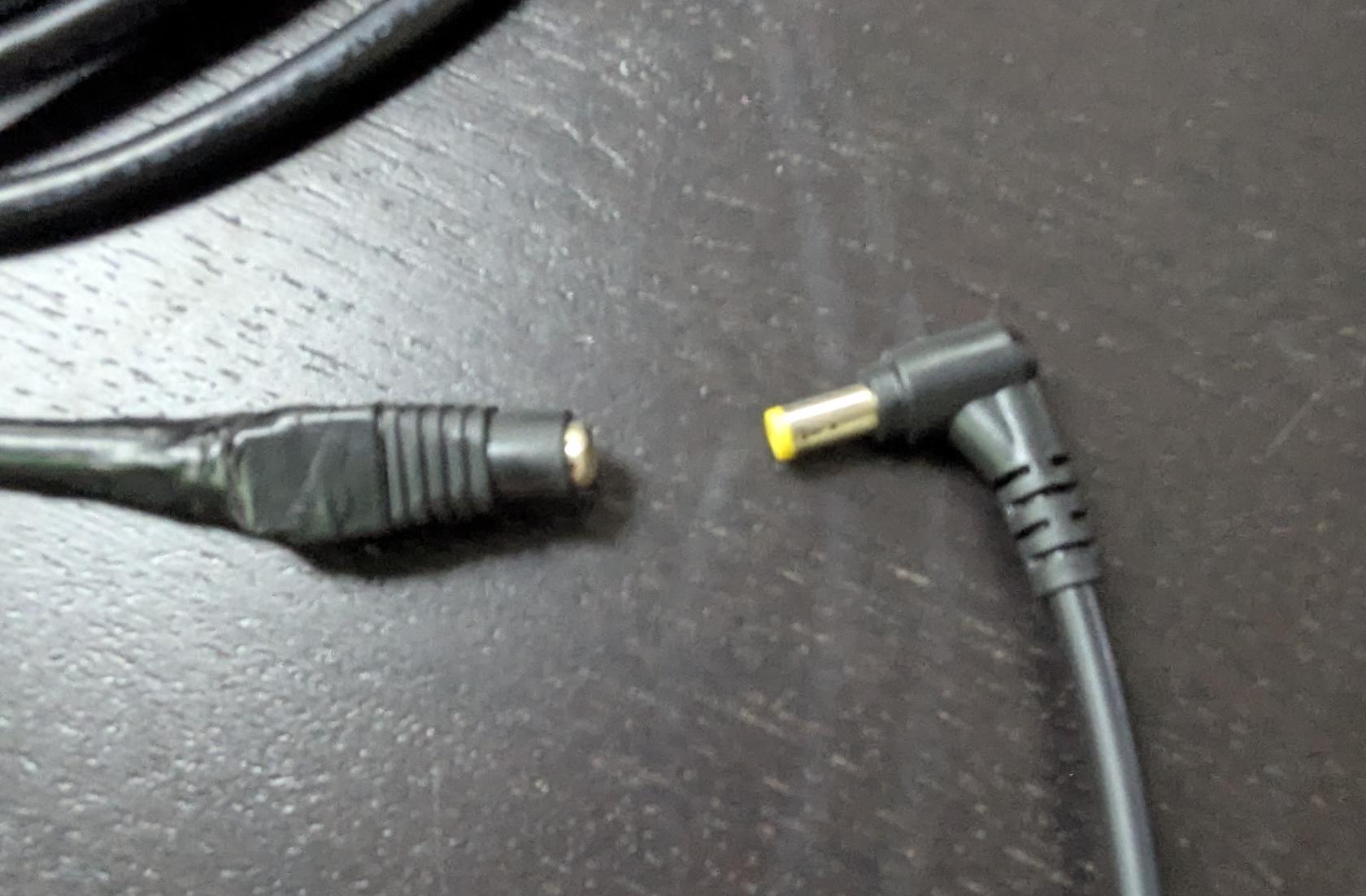](https://opscom.wiki/uploads/images/gallery/2025-08/pxl-20250730-182629557.jpg) - Align pins and attach the cord to the camera, as shown below: [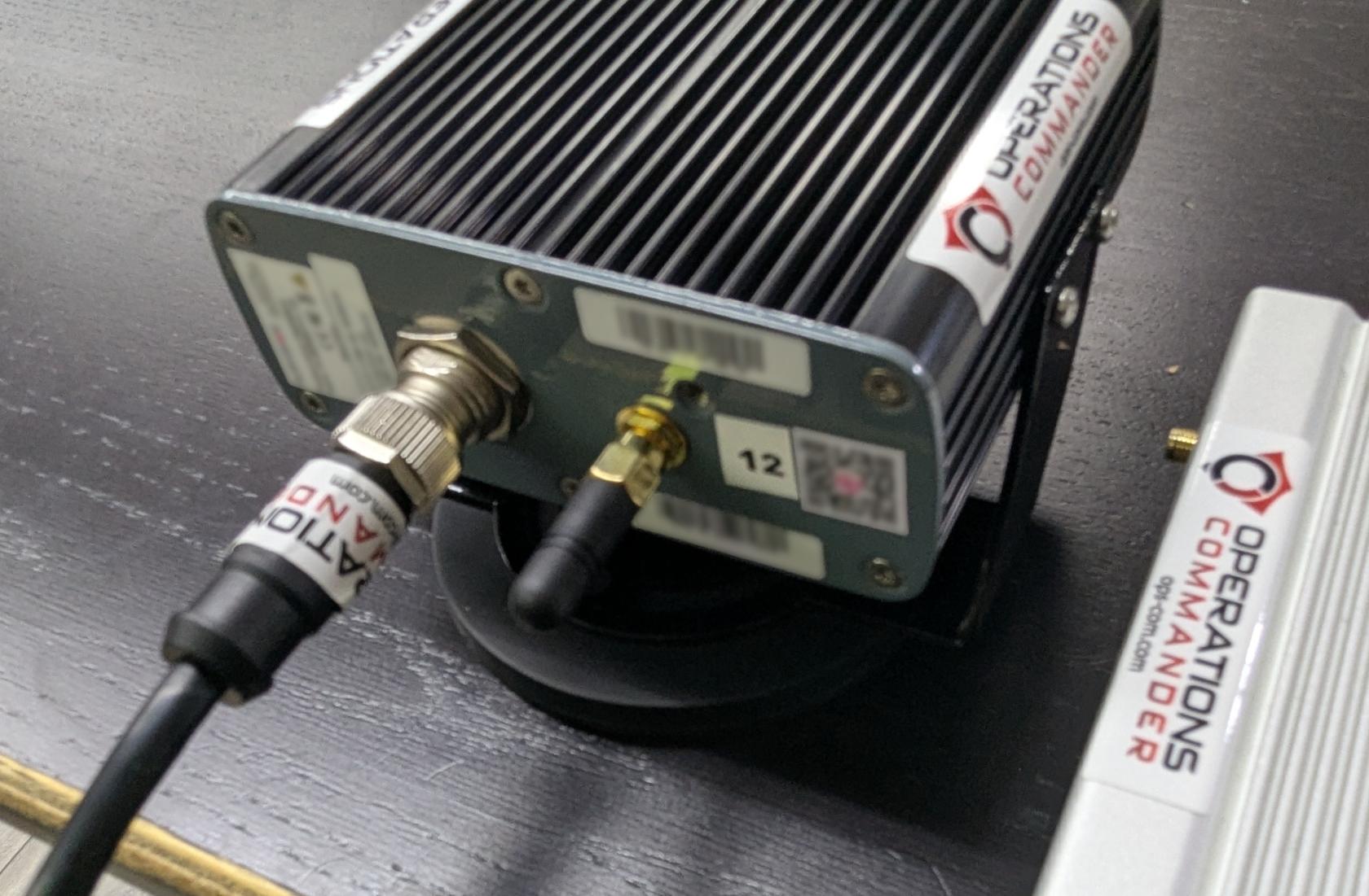](https://opscom.wiki/uploads/images/gallery/2025-08/pxl-20250730-182722145.jpg) - Plug in the other power source into the PL8RDR. Your setup should look like the picture below: [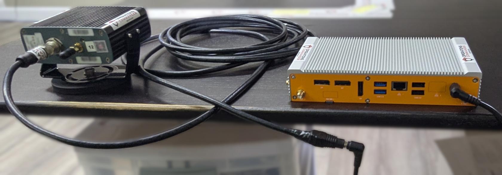](https://opscom.wiki/uploads/images/gallery/2025-08/pxl-20250730-182948033.jpg)You will know that you have succeeded once you see the camera emit a strong light.
Now you'll need to attach the antennas to the PL8RDR. This establishes a connection to the OPSCOM servers.All antennas need to be attached as shown or the device will not function as intended.
Here are the 3 antennas that you will need, as pictured below: - 2 x LAN Antennas - 1 x OPSCOM Wireless Connection Antennas [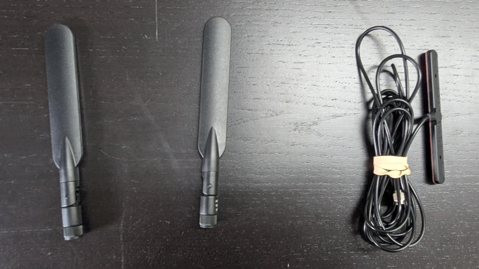](https://opscom.wiki/uploads/images/gallery/2025-08/pxl-20250730-183059617.jpg) - Attach the cable antennas to the port on the back left of the PL8RDR, as shown below: [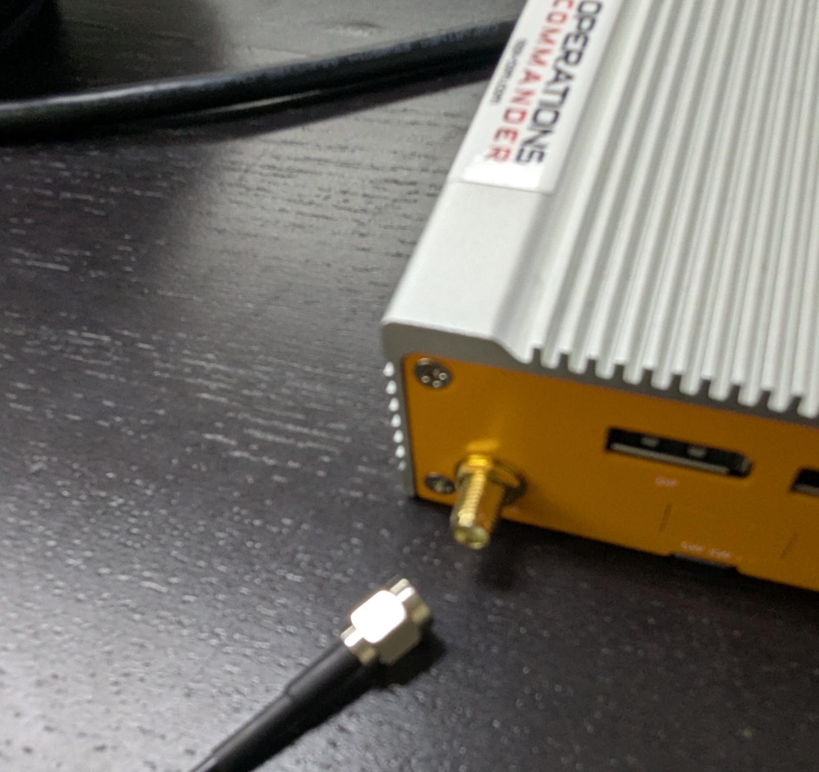](https://opscom.wiki/uploads/images/gallery/2025-08/pxl-20250730-183236060.jpg) - Lightly screw in the antennas on the side of the PL8RDR, as shown below. [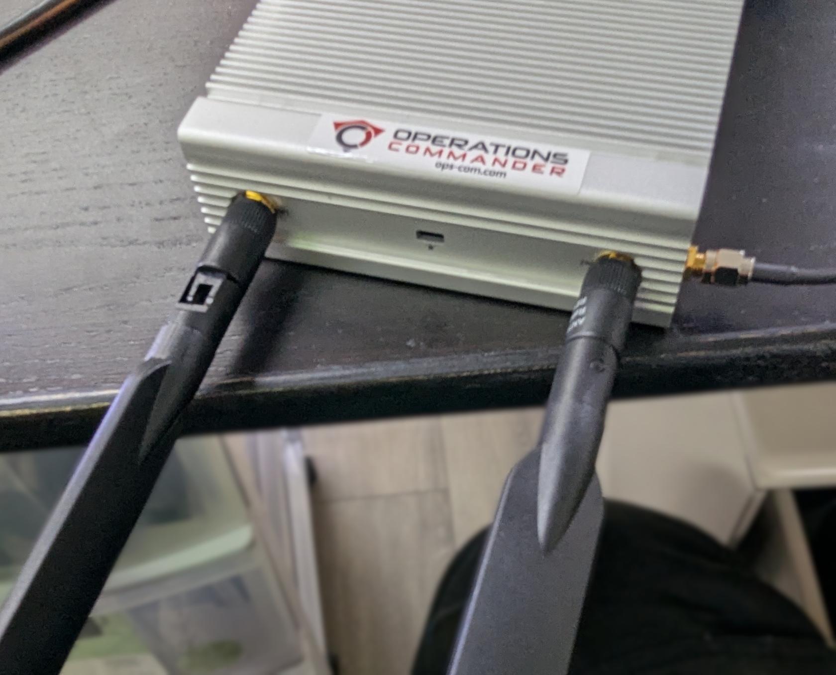](https://opscom.wiki/uploads/images/gallery/2025-08/pxl-20250730-183623099.jpg) - Make sure that the hinge is facing in the correct direction, as shown below, and gently fold the antennas into the upright position. [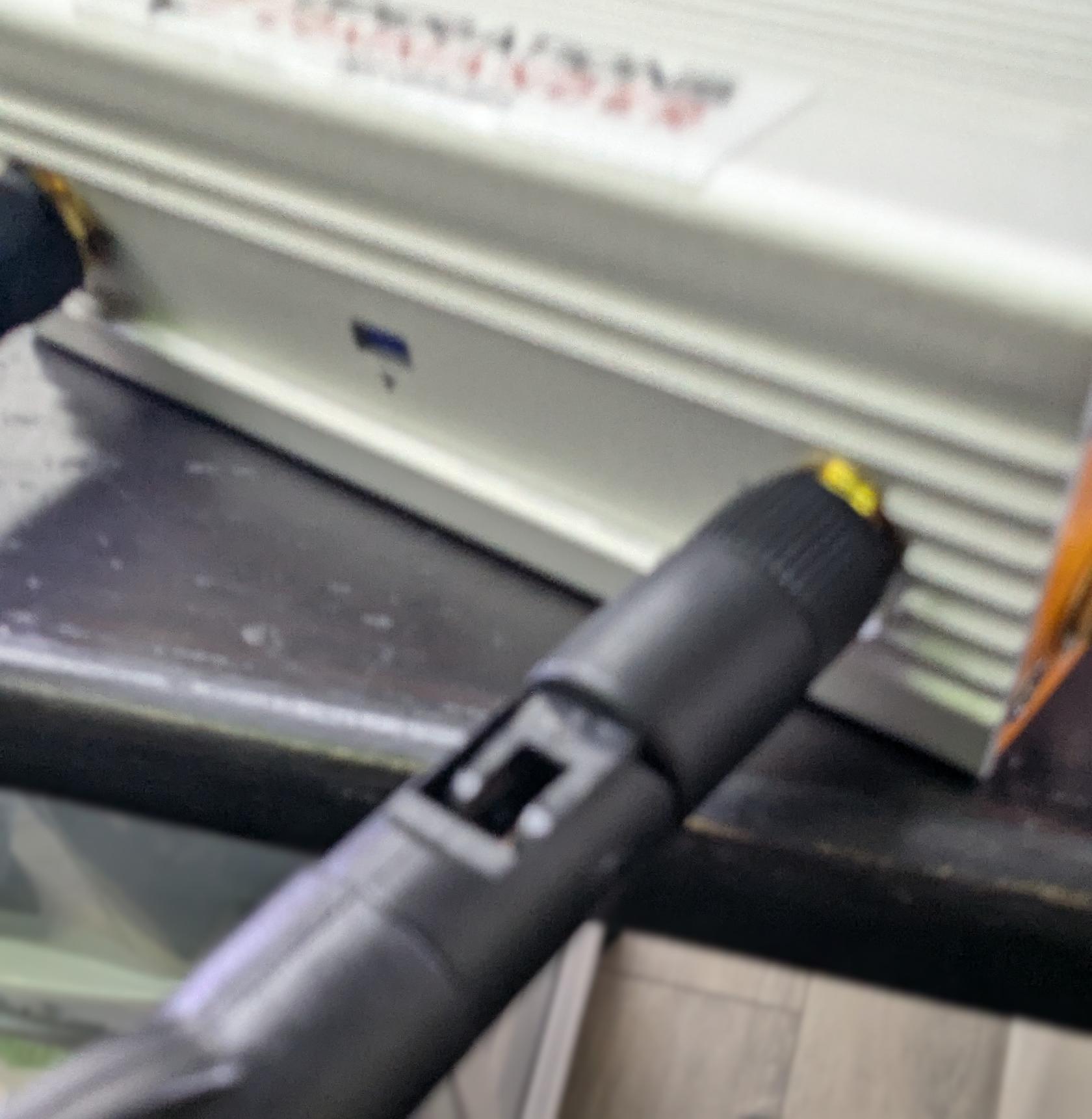](https://opscom.wiki/uploads/images/gallery/2025-08/pxl-20250730-183632241.jpg) - Make sure to place the corded antennas in an elevated location with a good data signal to ensure proper connectivity. This is what you should have when you’re done: [](https://opscom.wiki/uploads/images/gallery/2025-08/JRfpxl-20250730-183742139.jpg) # Part 2: Handheld Set-Up - Select the OPSCOM app on your device. - Log in with your OPSCOM admin username and password. - For this demo, use: - **Username:** `trial-demo-user` - **Password:** `hC8~1H0o` [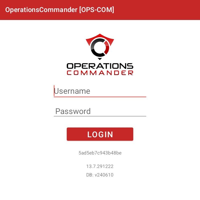](https://opscom.wiki/uploads/images/gallery/2025-09/screenshot-20250806-141803-operationscommander.jpg)