The LPR Kit Unboxing guide outlines the standard hardware components included when purchasing a complete Mobile License Plate Recognition (LPR) package. Its primary purpose is to help administrators and installers verify they have received all necessary equipment before beginning the physical vehicle installation process. This article is intended for OPSCOM administrators and field deployment staff.
## Setup and Configuration When you receive your Mobile LPR kit, it will include a detailed packing list specific to your shipment. Ensure you have a clean, organized workspace to carefully unpack and inventory the equipment before proceeding to the hardware configuration and vehicle installation phases. ## Included Equipment Checklist Please unpack your shipment carefully and ensure you have all the following components: - **Android tablet:** 1x unit sent in its factory box. The device charger will be included inside the box. - **Bluetooth printer:** 1x unit sent in its factory box. This typically includes a charger and one roll of blank receipt paper. - **Survision Picopak LPR camera:** 1x camera unit. - **Installer pack:** 1x pack containing all necessary connectors and power cables. This includes a DC 12 V car adapter and a cable splitter. - **PL8RDR computer:** 1x computing unit sent in its factory box. This hardware package typically includes: - Power adapter (AC to DC 12 V; 5.5 mm x 2.5 mm barrel connector male end) - 2x Wi-Fi antennas - 2x 4G LTE antennas (T-bar) - Mounting equipment - **SIM card:** 1x provisioned SIM card.The provided SIM card is typically pre-inserted directly into the PL8RDR computer unit prior to shipping. You do not need to locate or install it manually unless otherwise specified on your packing list.
--- ## Best Practices and Considerations - **Verify against the packing list:** **Always cross-reference your received items with the detailed packing list included in your shipment.** If any items are missing, contact OPSCOM support immediately before beginning your installation. - **Retain factory packaging:** **Keep all factory boxes and packaging materials.** These are highly useful and often required if any hardware needs to be returned for warranty repairs or an RMA (Return Merchandise Authorization) in the future. - **Handle components with care:** **Treat all LPR camera and computing equipment with care to prevent electrostatic discharge or physical damage during the unboxing phase.** # Part 1: Getting an Installer & Cable Modifications (Optional)The Installer and Cable Modifications process outlines the necessary physical cabling setup required to power Mobile License Plate Recognition (LPR) cameras and the PL8RDR computer within an enforcement vehicle. Its primary purpose is to ensure all hardware is correctly wired, powered, and integrated for reliable field operation. This article is intended for OPS-COM administrators and professional vehicle equipment installers.
## Setup and Configuration This process requires a professional installer to set up all required vehicle cabling. Verify with your installer exactly how you want the system to function, as they will determine the optimal power routing and cabling layout for your specific vehicle fleet. **Installer Side:** Depending on your vehicle's hardwiring requirements, the standard cables provided in your kit may require physical modification.**Your installer may have to modify the provided factory cables.** The Survision camera cable includes a standard car adapter which may need to be cut off and replaced with the 12V 5.5x2.5 Male-Female Power Plug to ensure a direct and stable power connection.
## Cable Configuration Installers can use the following connectivity instructions to accurately route power and data between the vehicle, the cameras, and the PL8RDR computer based on the specific splitter cables included in your hardware kit. ### M12 Y-Splitter Configuration If your hardware setup includes the standard Survision cable and the M12 Y-Splitter, ensure the physical connections match the following configuration: 1. Connect terminal **A** directly to the power input. 2. Connect terminal **B** directly to the LPR Camera. 3. Connect terminal **PC** directly to the PL8RDR computer. [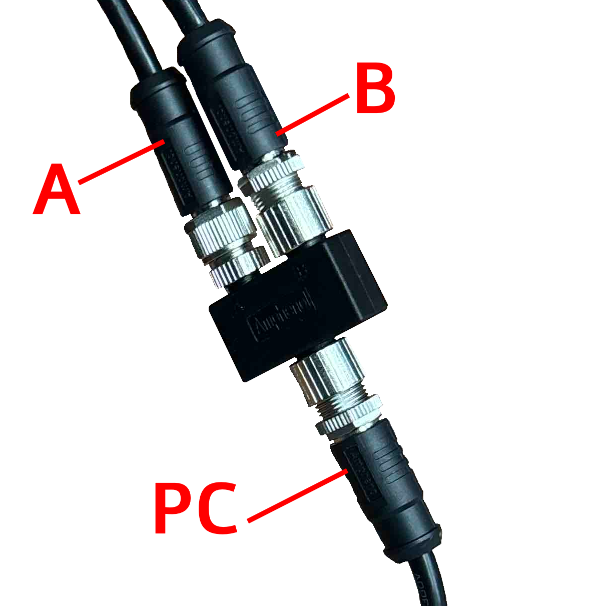](https://opscom.wiki/uploads/images/gallery/2026-07/8q4camera-connection-diagram.png) ### Standard DC Y-Splitter Configuration If your hardware setup utilizes the 12V Car Cigarette Lighter to DC Barrel Jack and a 1-to-3 DC Y-Splitter, the connectivity follows a highly simplified route: 1. Connect terminal **A** to LPR Camera 1. 2. Connect terminal **B** to LPR Camera 2. 3. Connect terminal **C** directly to the PL8RDR computer. 4. Connect the **12V Car Cigarette Lighter Jack** directly into the vehicle's 12V auxiliary power outlet. [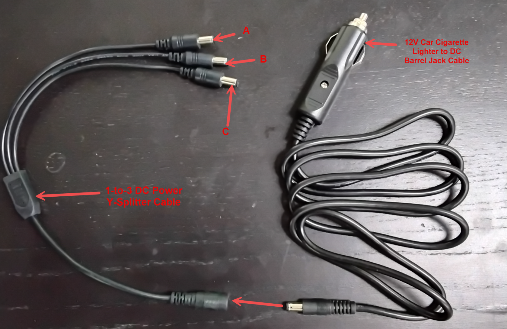](https://opscom.wiki/uploads/images/gallery/2026-05/image.png) --- ## Best Practices and Considerations - **Provide the specification document:** **Ensure your installer is provided with the PICOPAK3 PINOUT and CONNECTIONS specification document here [PICOPAK3 PINOUT & CONNECTIONS\_English.pdf](https://opscom.wiki/PICOPAK3%20PINOUT%20&%20CONNECTIONS_English.pdf).** This is absolutely crucial for verifying pinouts and maintaining hardware warranty standards during any custom modification. - **Verify power requirements:** **Verify the consistent power draw and electrical requirements with your installer.** Mobile LPR equipment requires stable power; improper connections or insufficient voltage can lead to unexpected system reboots or data loss during active enforcement patrols. - **Secure all physical connections:** **Ensure all cable connections are securely fastened and protected from physical wear or environmental exposure.** Routing cables safely and neatly within the vehicle cab prevents accidental disconnection by enforcement officers entering and exiting the vehicle. # Part 2: Equipment Set-UpThe Mobile LPR Equipment Setup process outlines the physical connection and configuration of your License Plate Recognition hardware. Its primary purpose is to ensure the Survision camera, PL8RDR computer, and associated peripherals are correctly powered and positioned for accurate plate scanning. This article is intended for OPSCOM administrators and field deployment staff responsible for installing the LPR kit.
## Setup and Configuration This process requires direct physical interaction with the provided hardware components. A typical setup includes a Survision LPR camera, a PL8RDR micro-computer (the "brains" of the operation), a 4G/LTE tablet, a Bluetooth printer, and a vehicle mount. **Powering the PL8RDR:** The PL8RDR computer requires a strictly 12V DC power source and must always be connected using an inline fuse to protect the hardware. It can be powered using a vehicle power adapter for field use or a standard wall plug for in-office testing. The setup steps below apply to both power options. ## Connecting the Equipment Installers can use the following instructions to accurately route power and attach the required communication antennas to the PL8RDR and camera. [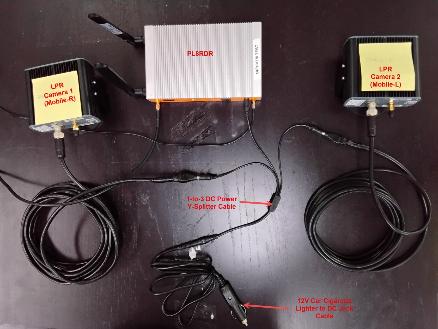](https://opscom.wiki/uploads/images/gallery/2026-05/TFT20260501-113731.jpg) ### Connecting the Power and Camera 1. Connect the splitter to the primary power cord. 2. Plug the opposite end of the power cord into the wall socket or the vehicle power adapter. 3. Connect one of the split power cords to the LPR data/power cord. 4. Align the pins and attach the cord securely to the Survision camera. 5. Plug the remaining power source directly into the PL8RDR computer.You will know that the initial power setup is successful when the Survision camera emits a strong, visible light.
### Installing the Antennas The system utilizes two LAN antennas and one OPSCOM wireless connection antenna. 1. Attach the corded LAN antennas to the specific port on the back left of the PL8RDR. 2. Lightly screw the side antennas into their designated ports on the side of the PL8RDR chassis. 3. Gently fold the side antennas into an upright position, ensuring the hinge is facing the correct direction. 4. Mount or place the corded LAN antennas in an elevated location within the vehicle to ensure a strong data signal.All antennas must be attached correctly and securely. If they are omitted or improperly connected, the device will not establish a connection to the OPSCOM servers and will fail to function as intended.
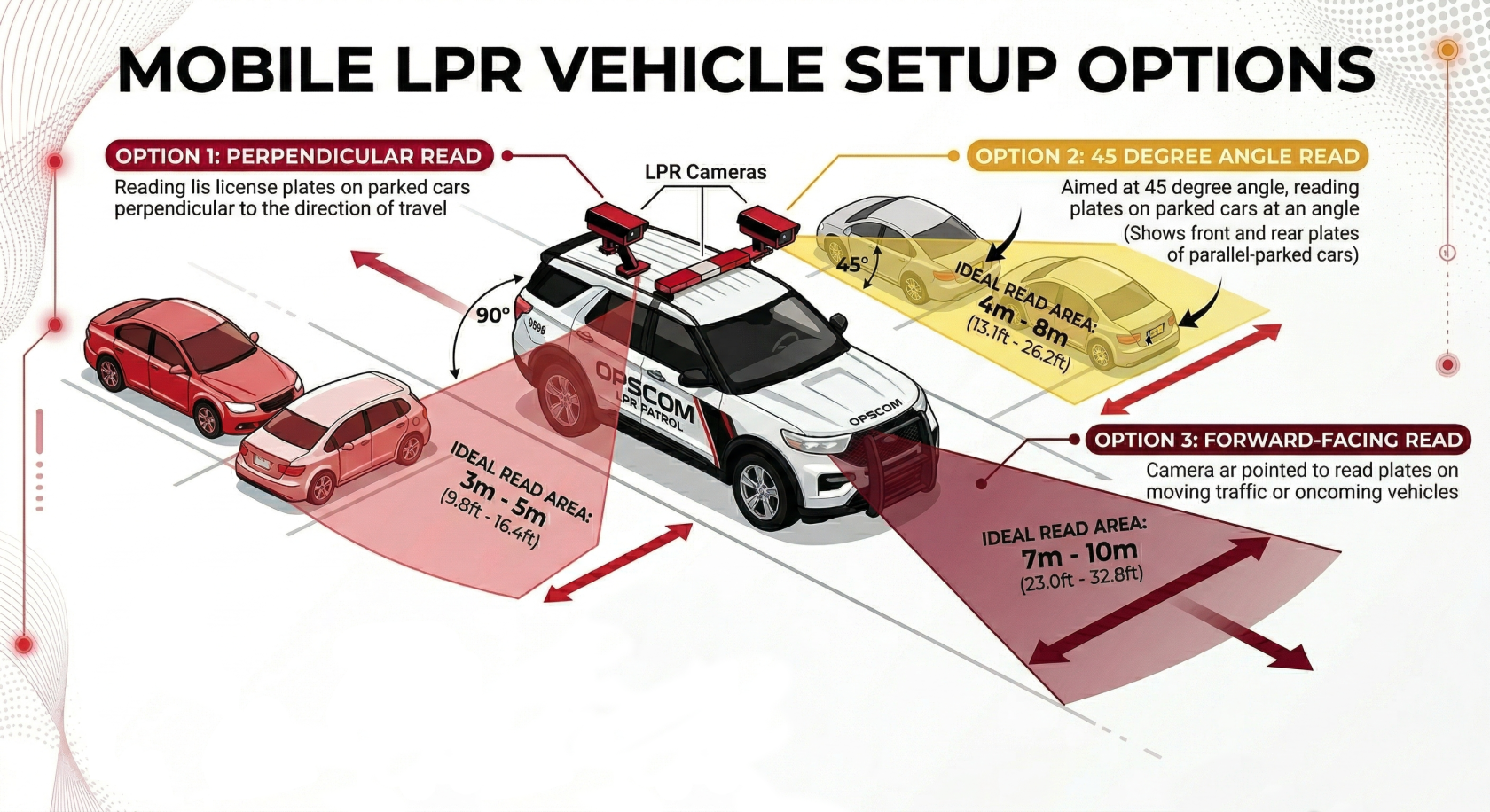
## [Positioning the Survision Camera](https://opscom.wiki/books/lpr-cameras-setup-playbook/page/setting-up-your-survision-lpr-camera) Proper camera positioning is critical for accurate license plate reads. Installers must physically align the camera and use the software configuration assistant to finalize the setup. 1. Park your enforcement vehicle behind and to the side of a reference vehicle with a clearly visible license plate (simulating driving past it on the street). 2. Mount the camera on your vehicle so it is physically between 3 and 8 meters away from the reference plate. 3. Angle the camera so it is offset less than 30 degrees from the plates you are scanning. 4. Connect a mobile device or laptop to the **pl8rdr.opscom** Wi-Fi network. 5. Open a web browser and enter the camera’s IP address to access the management interface. 6. Click **Configuration assistant**. 7. Click the **Next** button to navigate through the first three screens. 8. Adjust the physical camera on your vehicle during the fourth screen until the reference plate is perfectly centered in the green box on your screen. 9. Verify that the lines of text above the camera feed all turn green, indicating the camera is correctly positioned. 10. Click the **Next** button to proceed. 11. Leave the fields blank on the final screen and click the **Finish** button.You may see a system error message after clicking the final button, but you can safely ignore it. The required address is automatically configured on the PL8RDR.
[](https://opscom.wiki/uploads/images/gallery/2026-03/mobile-lpr-camera-setup-options.png) --- ## Best Practices and Considerations - **Secure the hardware appropriately:** **Ensure the PL8RDR micro-computer is safely stored in the vehicle's trunk or a secure, well-ventilated compartment.** - **Retain the extra antenna:** **Keep the extra wireless connection T-Bar antenna on hand.** While not required for initial setup, it can be utilized later if you experience persistent connectivity issues in low-signal patrol areas. - **Optimize antenna placement:** **Make sure to place the corded antennas in an elevated location with a good data signal.** Surrounding metal from the vehicle body can interfere with transmission if the antennas are buried too deeply in the trunk or cab. - **Maintain strict camera angles:** **Strictly maintain a camera angle of less than 30 degrees off the target plates.** Steeper angles will significantly reduce OCR (Optical Character Recognition) read accuracy and result in missed enforcement opportunities. # Part 3: Handheld Set-UpThe Mobile LPR Handheld Setup process guides administrators through configuring Android tablets to successfully communicate with the LPR camera and the PL8RDR network. Its primary purpose is to establish the secure data link required for scanning license plates, processing vehicle data, and issuing violations in the field. This article is intended for OPSCOM administrators and field deployment staff.
## Setup and Configuration This process requires a compatible Android handheld unit and the OPSCOM Parking Enforcement app. **Admin Side:** Administrators must ensure the correct network configurations and IP addresses are applied to the handheld device so it can communicate seamlessly with the vehicle's LPR hardware. **User Side:** Field officers will connect their devices to the vehicle's local Wi-Fi network and log into the enforcement app to begin scanning plates during their patrol.If you purchased a fully configured tablet directly from OPSCOM, the enforcement app is pre-installed, the printer is already paired, and the camera IP is pre-configured. You can skip the IP configuration steps below and proceed directly to connecting to the PL8RDR network.
### Configuring the Camera IP (Bring Your Own Device) If you are using your own Android tablet, you must configure the camera IP address so the handheld can establish a direct data transfer link with the Survision camera. 1. Open the **OPSCOM Parking Enforcement** app on your device. 2. Tap **System Settings**. 3. Locate the **PicoPak Camera IPs** text box. 4. Enter the required IP address **10.42.0.11**. [](https://opscom.wiki/uploads/images/gallery/2026-07/1kGimage.png) ## Using this Feature Field officers and administrators can use the following instructions to connect the handheld device to the vehicle's hardware and test the system's core functionality. ### Connecting to the PL8RDR Network The PL8RDR computer acts as a mobile router, broadcasting a local Wi-Fi network that the handheld device uses to communicate with external systems. 1. Open the Wi-Fi settings menu on your Android device. 2. Tap the **pl8rdr.opscom** network from the list of available connections. 3. Enter the network password **T0maha3k**. 4. Tap the **Connect** button to establish the link. ### Accessing the Enforcement App 1. Tap the **OPSCOM Parking Enforcement** app icon to launch the software. 2. Enter your standard OPSCOM admin username and password. 3. Tap the **Login** button. ### Testing Core Functionalities Once logged in and connected to the hardware, you are ready to test the LPR system. The app offers several key features for active enforcement: - **Searching for Vehicles:** You can search for vehicles using three methods: tapping the search field to type the plate number manually, using voice commands, or utilizing the LPR camera with OCR technology for automated scanning. - **E-Chalking (Virtual Chalking):** This feature electronically tracks how long a vehicle has been parked. It creates a time-stamped image of the license plate and the entire car, which can be attached directly to a violation. - **Issuing Violations:** You can issue violations directly to a person or a vehicle profile. The system will automatically perform a secondary check and issue a warning prompt if a scanned plate has a valid permit, though it will still allow you to proceed with the violation at your discretion. --- ## Best Practices and Considerations - **Verify printer pairing:** **Ensure your Bluetooth printer is properly paired with the tablet before beginning a patrol.** If your printer was not purchased through OPSCOM and requires manual setup, refer to the relevant printer setup wiki article for detailed Bluetooth pairing instructions. - **Manage chalked images:** **Remember that the e-chalked image is permanently saved with the violation record unless you explicitly delete it.** This provides excellent visual evidence for dispute resolution. - **Monitor connectivity:** **Ensure the handheld remains connected to the pl8rdr.opscom network during patrols.** If the device drops this specific Wi-Fi connection, it will lose the ability to communicate with the LPR hardware. - **Consult troubleshooting guides:** **If you experience any connectivity or software issues, refer to the [Troubleshooting Tips](https://opscom.wiki/books/mobile-lpr-installation-manual/page/troubleshooting-tips).** Detailed steps are available to help resolve common hardware handshakes or app login errors.