
Part 2: Equipment Set-Up
Let's connect all the gear. A typical OPSCOM LPR system includes a Survision LPR camera, a PL8RDR device, a 4G/LTE tablet, a Bluetooth printer, and a vehicle mount.
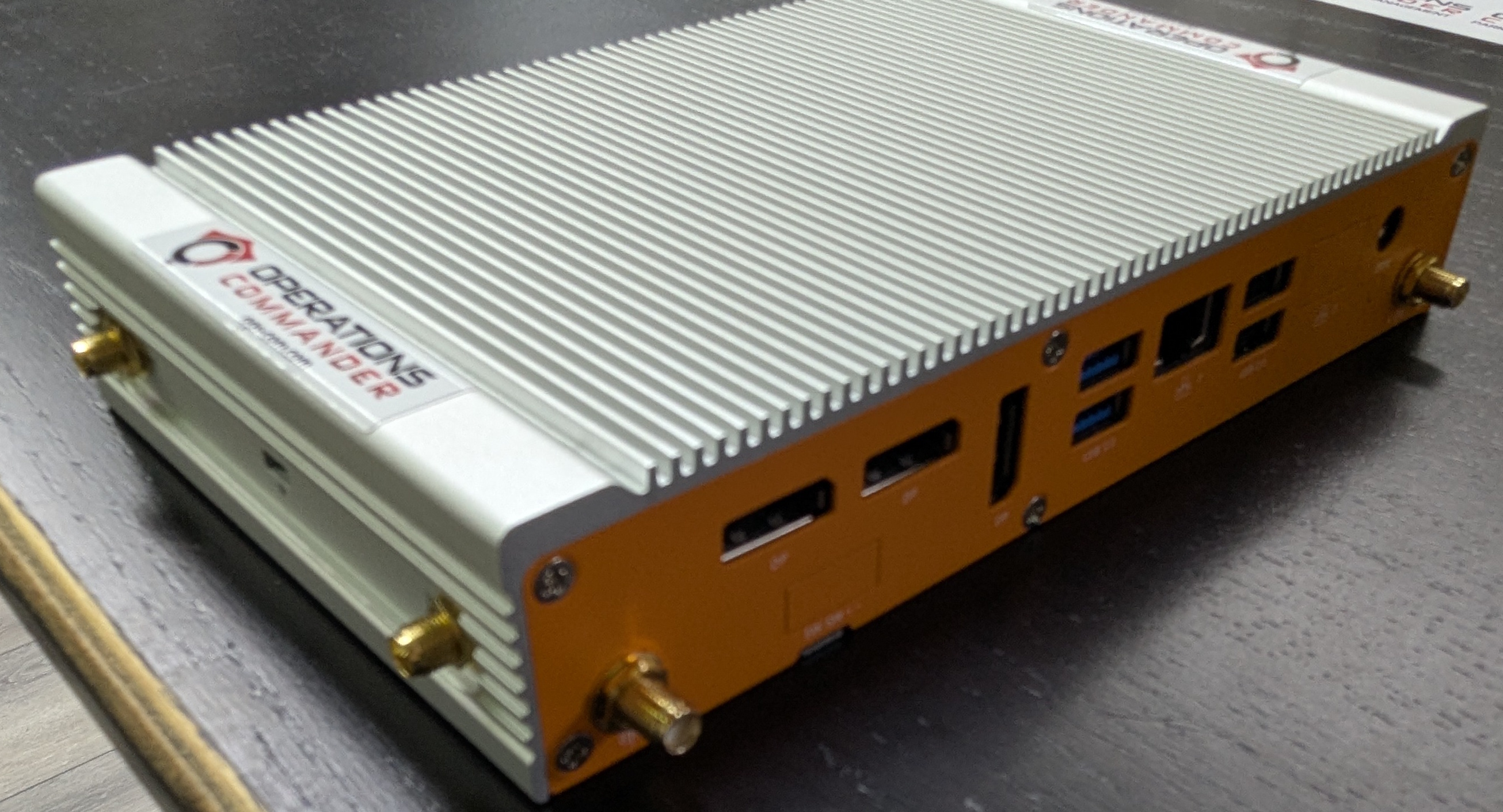
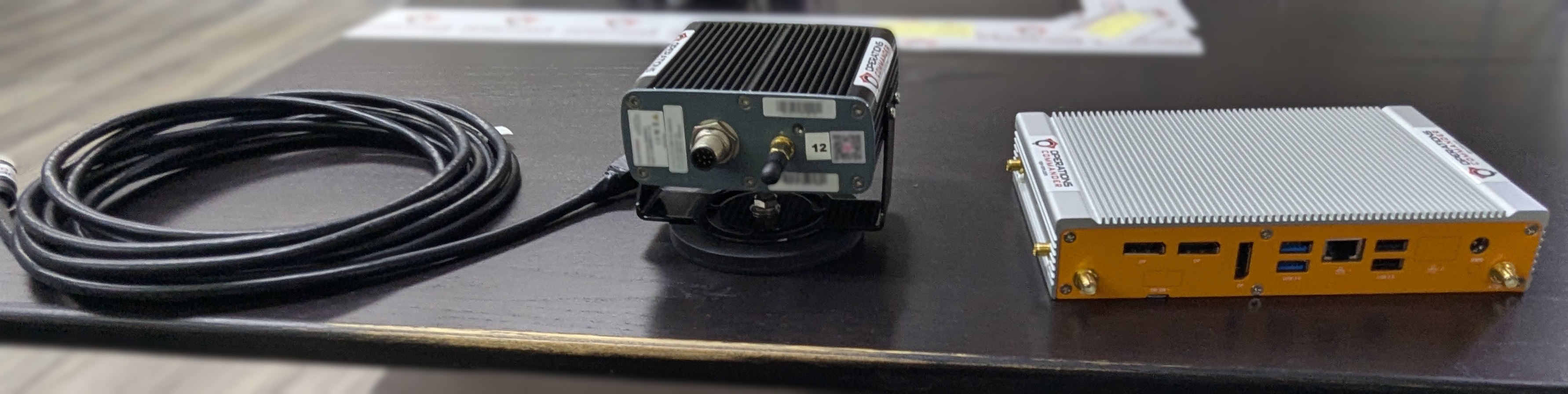
The PL8RDR - (LPR Computer)
This is the brains of the operation and is a small micro-computer that is normally stored in the vehicles truck.
Powering the PL8RDR
There are two options for powering the PL8RDR. The PL8RDR computer can be powered using a vehicle power adapter or a wall plug. The setup steps are the same for both options. The PL8RDR uses a 12V DC power source and should be connected with an inline fuse.
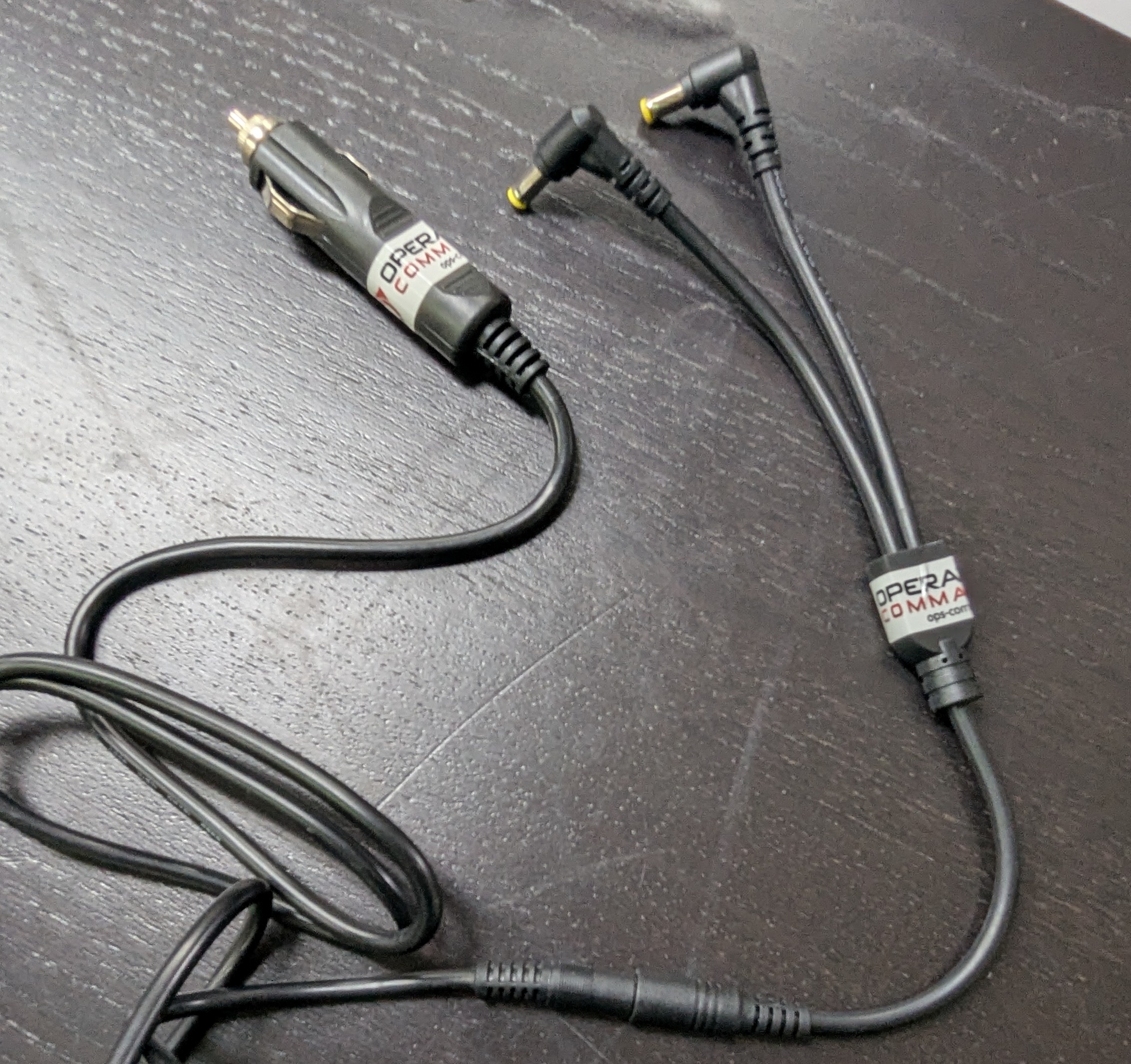
Option #1: Using the Vehicle Power Adapter
- Option #2: Using a wall plug.
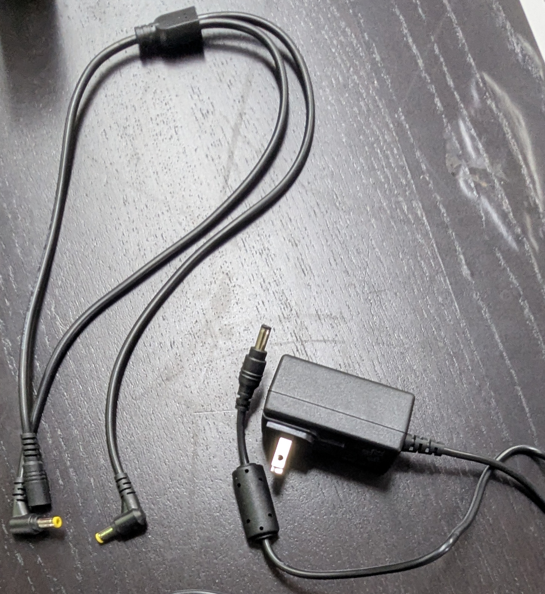
In this guide and pictured below, we are using Option #2: Using a wall plug. If you are setting this up in a vehicle, follow the exact same set-up steps but use the vehicle plug power adapter instead. The rest of the connections remain the same.
Step-by-Step
The Wall Power Cord
- Connect the splitter to the rest of the power cord, as shown below:
- Plug in the other side to the wall socket or the vehicle power adapter, depending on your setup.
- Next, get these 3 items ready:
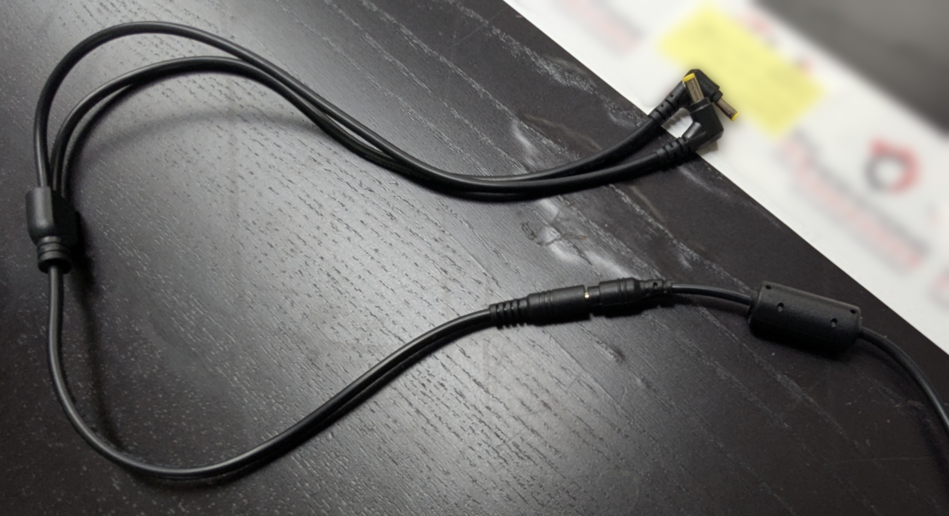
- LPR power/data cord
- Camera
- PL8RDR computer
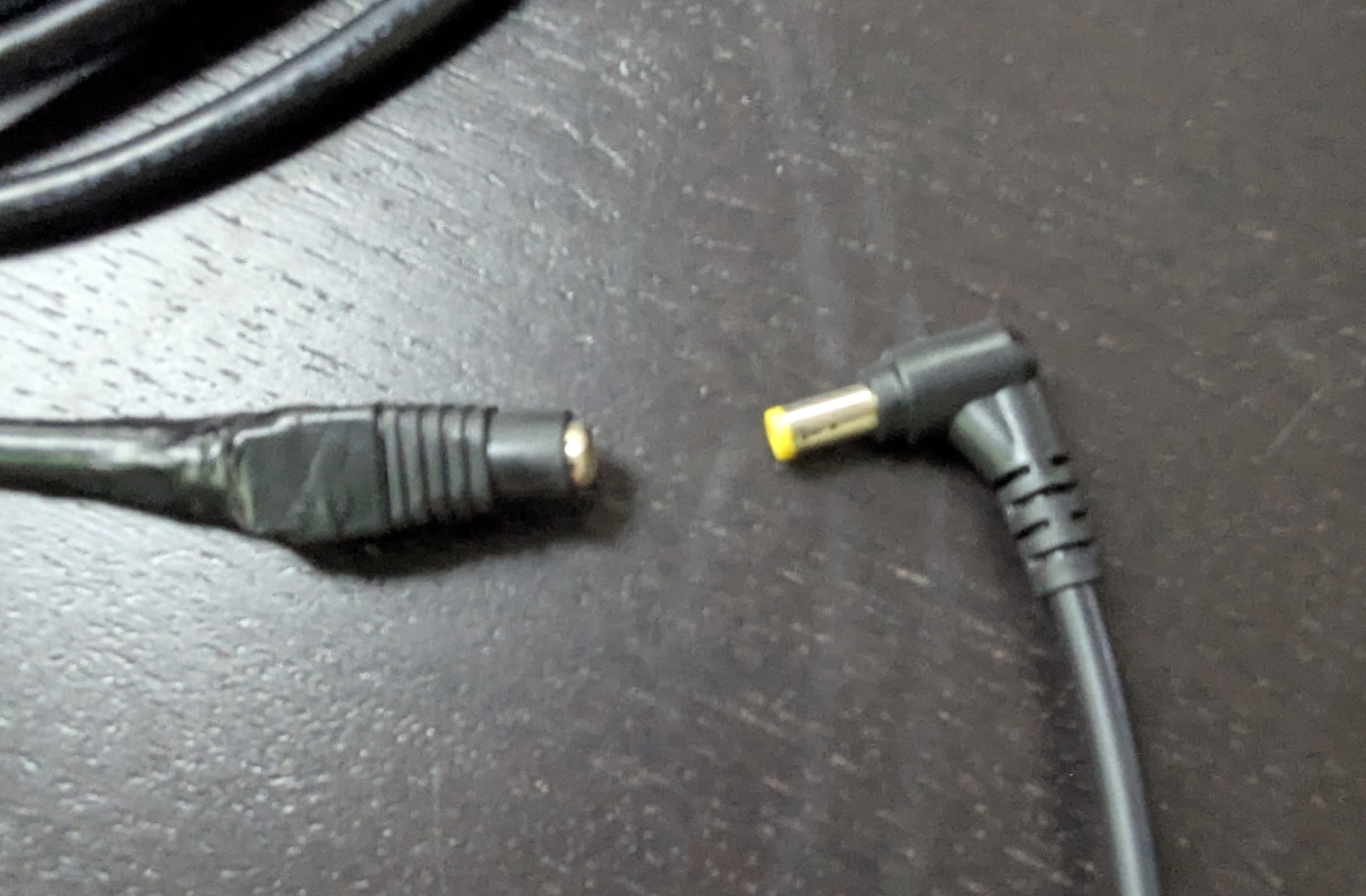
Notice the two different ends on the LPR power/data cord. Pictured below:
The cable shown above may vary depending on your setup. This version includes a female barrel plug connector.
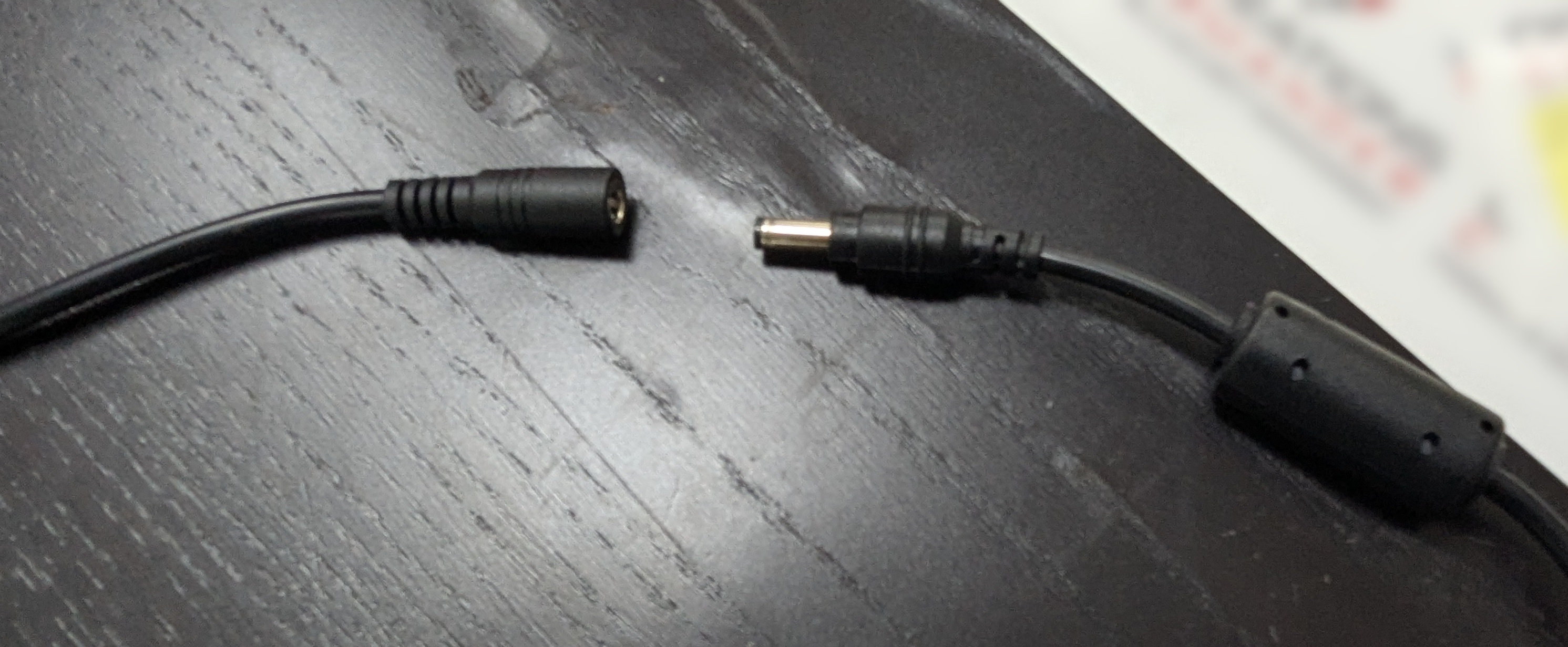
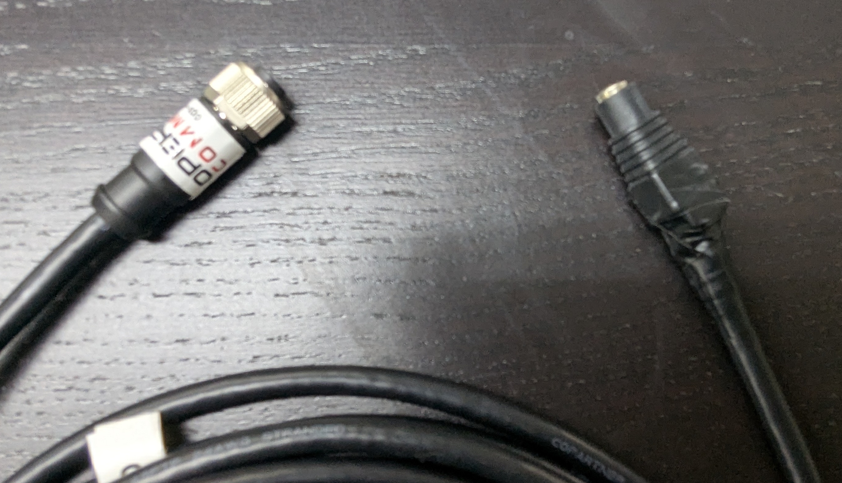
- Connect one of the power cords to the LPR data/power cord, as shown below:
- Align pins and attach the cord to the camera, as shown below:
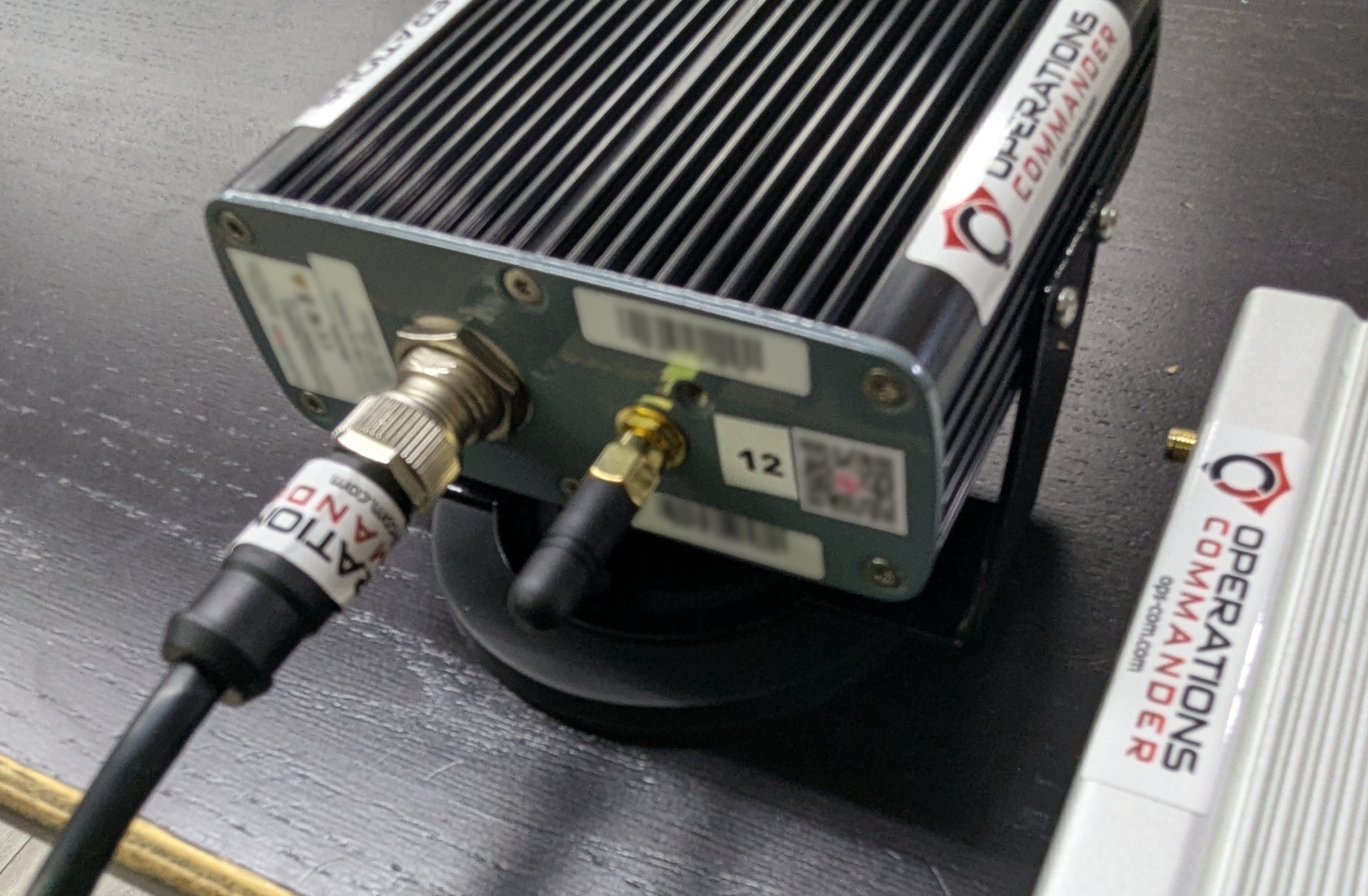
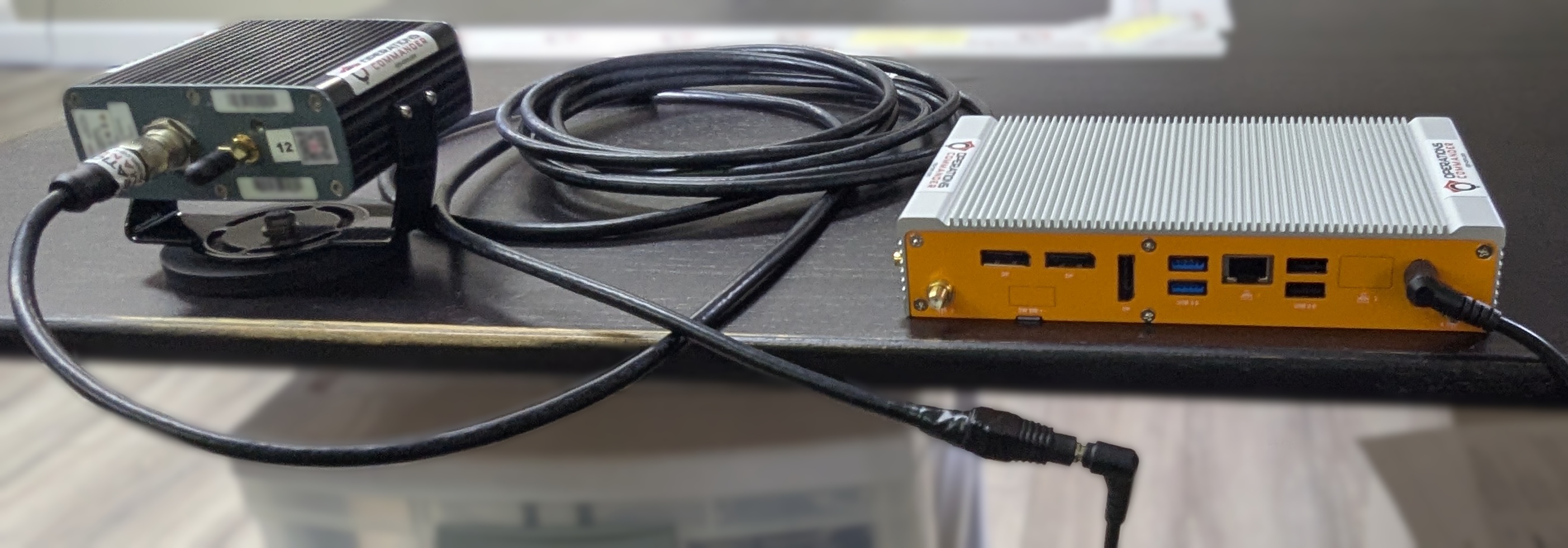
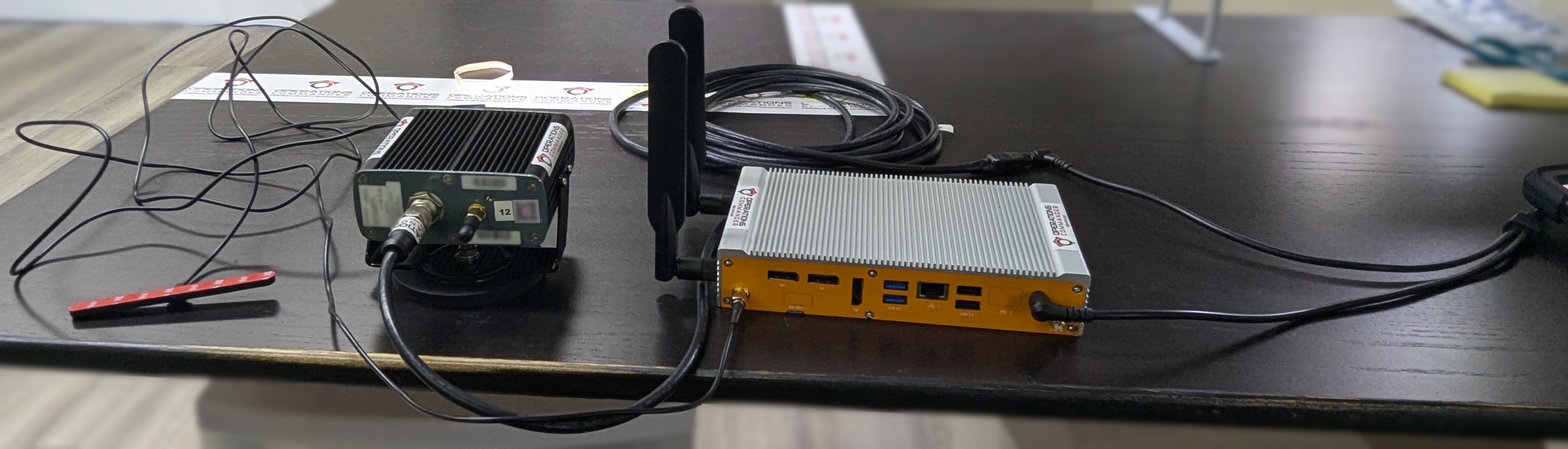
- Plug in the other power source into the PL8RDR. Your setup should look like the picture below:
You will know that you have succeeded once you see the camera emit a strong light.
Now you'll need to attach the antennas to the PL8RDR. This establishes a connection to the OPSCOM servers.
All antennas need to be attached as shown or the device will not function as intended.
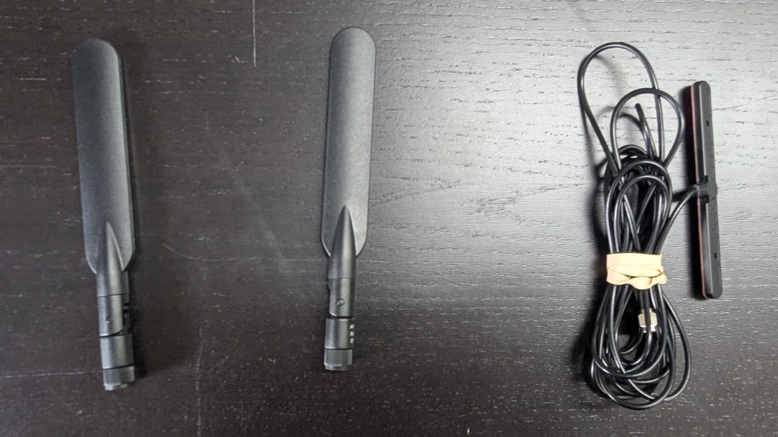
Here are the 3 antennas that you will need, as pictured below:
- 2 x LAN Antennas
- 1 x OPSCOM Wireless Connection Antennas
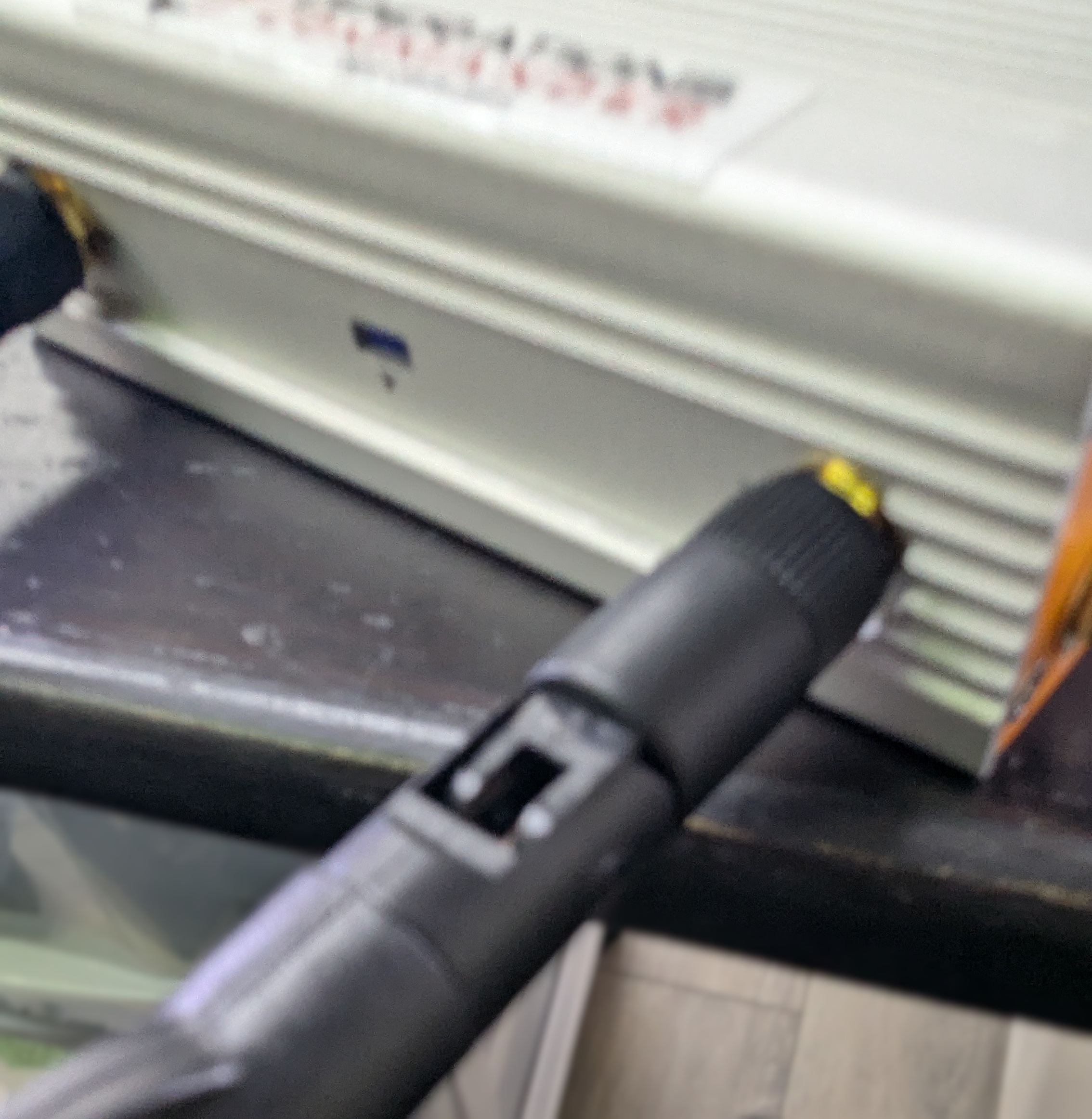
- Attach the cable antennas to the port on the back left of the PL8RDR, as shown below:
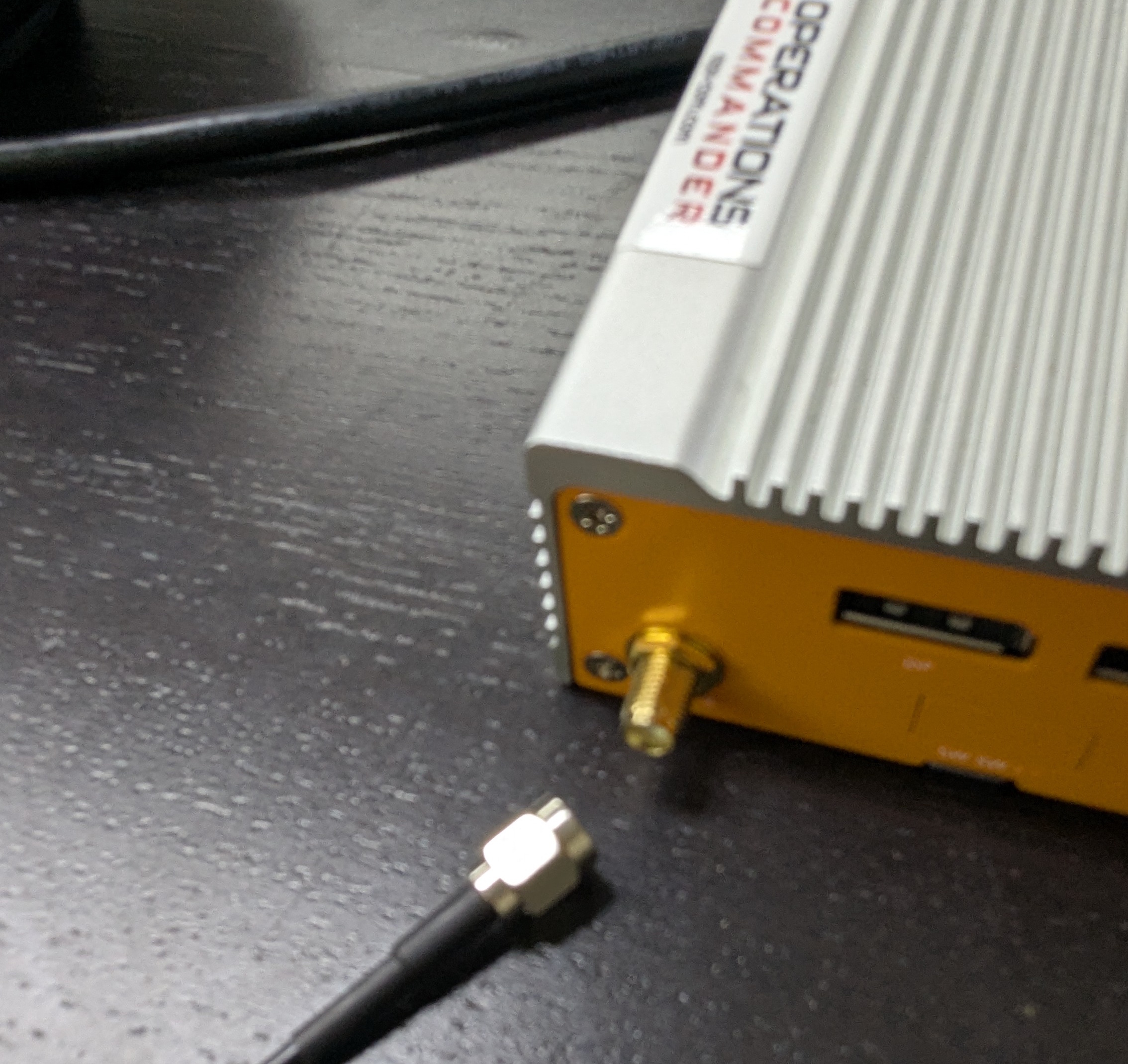
- Lightly screw in the antennas on the side of the PL8RDR, as shown below.
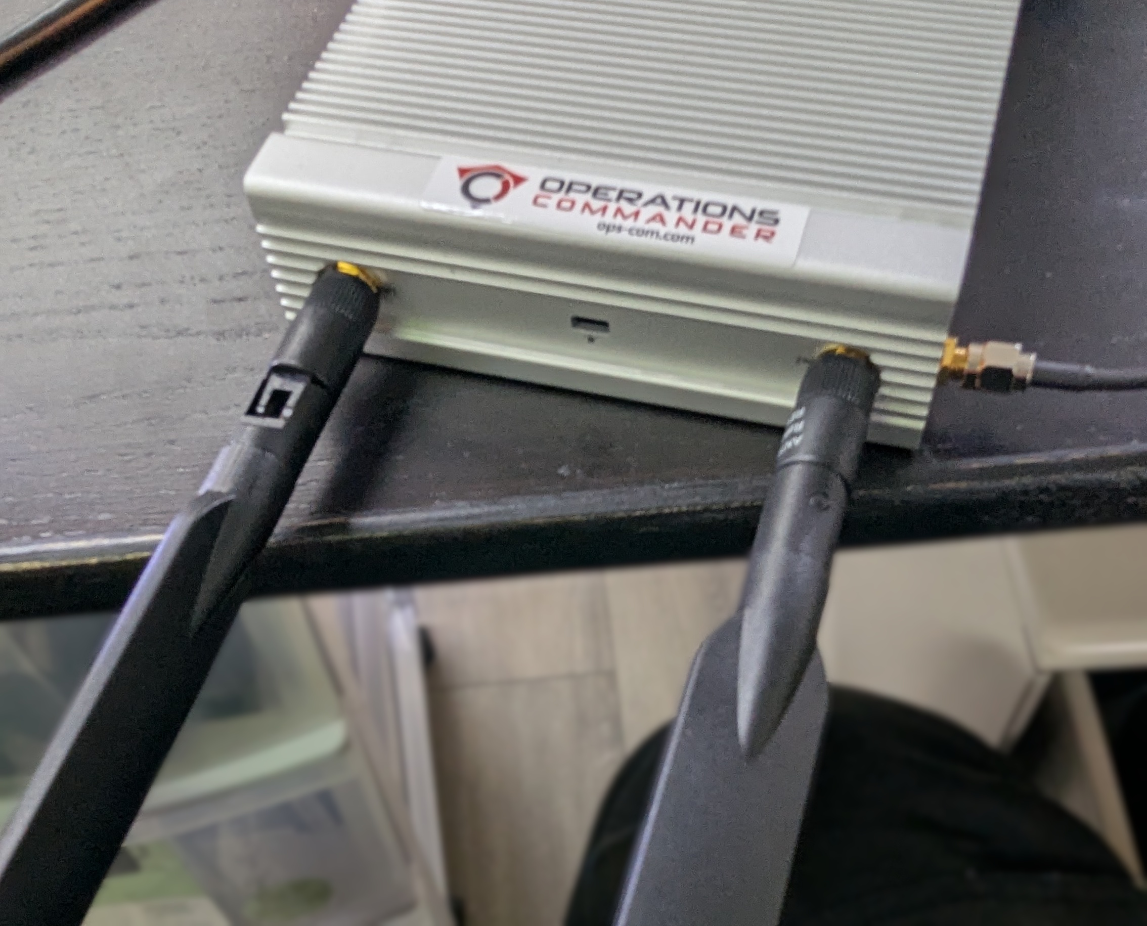
- Make sure that the hinge is facing in the correct direction, as shown below, and gently fold the antennas into the upright position.
- Make sure to place the corded antennas in an elevated location with a good data signal to ensure proper connectivity. This is what you should have when you’re done:
Positioning the Survision Camera
Proper camera positioning is critical for accurate license plate reads. Follow these steps to get it just right:
- Find Your Reference: Choose a vehicle with a license plate to use as your reference point.
- Position Your Vehicle: Park your enforcement vehicle behind and to the side of the reference car, as if you were driving past it on the street.
- Camera Placement: The camera on your vehicle should be approximately 5 meters away from the reference plate. It should also be angled less than 30 degrees off the front of the plate, both vertically and horizontally.
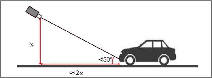 (This diagram shows a vertical angle, but the same applies horizontally.)
- Use the Configuration Assistant: On a device connected to the
pl8rdr.opscomWi-Fi network, open a web browser and enter the camera’s IP address. Click on "Configuration assistant". - Set the Camera Angle: Follow the prompts by clicking "Next" through the first three screens. On the fourth screen, you will be asked to set the camera angle. Adjust the camera on your vehicle until the reference plate is centered in the green box on your screen. The lines of text above the camera feed should all turn green when it is correctly positioned.
- Finish Setup: Click "Next" when you're done. On the final screen, leave the fields blank and click "Finish". You may see an error message, but you can safely ignore it, as the address is configured on the PL8RDR.