
Part 1: Getting an Installer & Cable Modifications (Optional)
FirstThe thingsInstaller first,and findCable anModifications installerprocess tooutlines the necessary physical cabling setup all the cabling you need in your vehiclerequired to power theMobile License Plate Recognition (LPR) cameras and the PL8RDR.PL8RDR computer within an enforcement vehicle. Its primary purpose is to ensure all hardware is correctly wired, powered, and integrated for reliable field operation. This article is intended for OPS-COM administrators and professional vehicle equipment installers.
Setup and Configuration
This process requires a professional installer to set up all required vehicle cabling. Verify with your installer exactly how you want yourthe setupsystem to function.function, Theyas they will bedetermine ablethe tooptimal decidepower howrouting and cabling layout for your newspecific equipmentvehicle gets powered and how everything gets cabled.fleet.
PleaseInstaller note:Side: Depending on your vehicle's hardwiring requirements, the standard cables provided in your kit may require physical modification.
Your installer may have to modify the provided factory cables. The Survision Cameracamera cable hasincludes a standard car adapter which couldmay need to be cut off,off and replaced with the 12V 5.5x2.5 Male-Female Power Plug putto ensure a direct and stable power connection.
Cable Configuration
Installers can use the following connectivity instructions to accurately route power and data between the vehicle, the cameras, and the PL8RDR computer based on the specific splitter cables included in itsyour place.hardware kit.
SurvisionM12 CameraY-Splitter Cable
Configuration
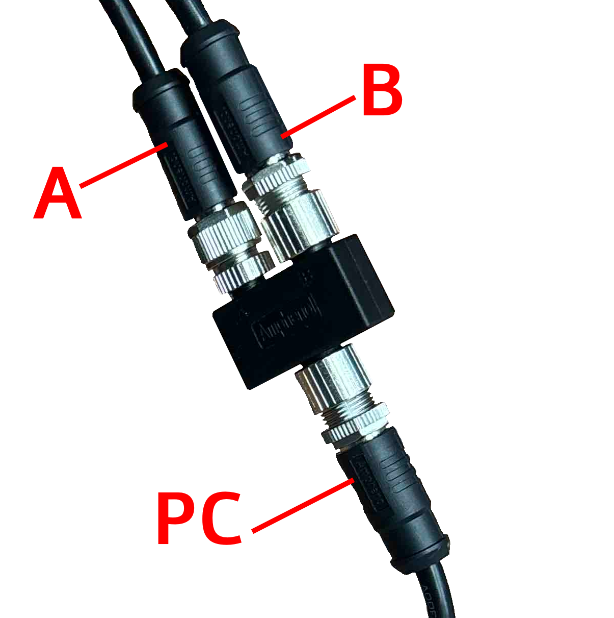
Youryourinstallerhardwaremaysetupneed to refer toincludes thepin/cable specification document available here:PICOPAK3 PINOUT & CONNECTIONS_English.pdfIf you have thestandard Survision cable and the M12 Y-Splittershown below, pleaseSplitter, ensurethesethearephysical connections match theconnections:following configuration:-
Connect terminal A directly to the power input.
-
If
Connect terminal B directly to the LPR Camera. Connect terminal PC directly to the PL8RDR computer.
| DC Y-Splitter
Configuration
|
- If
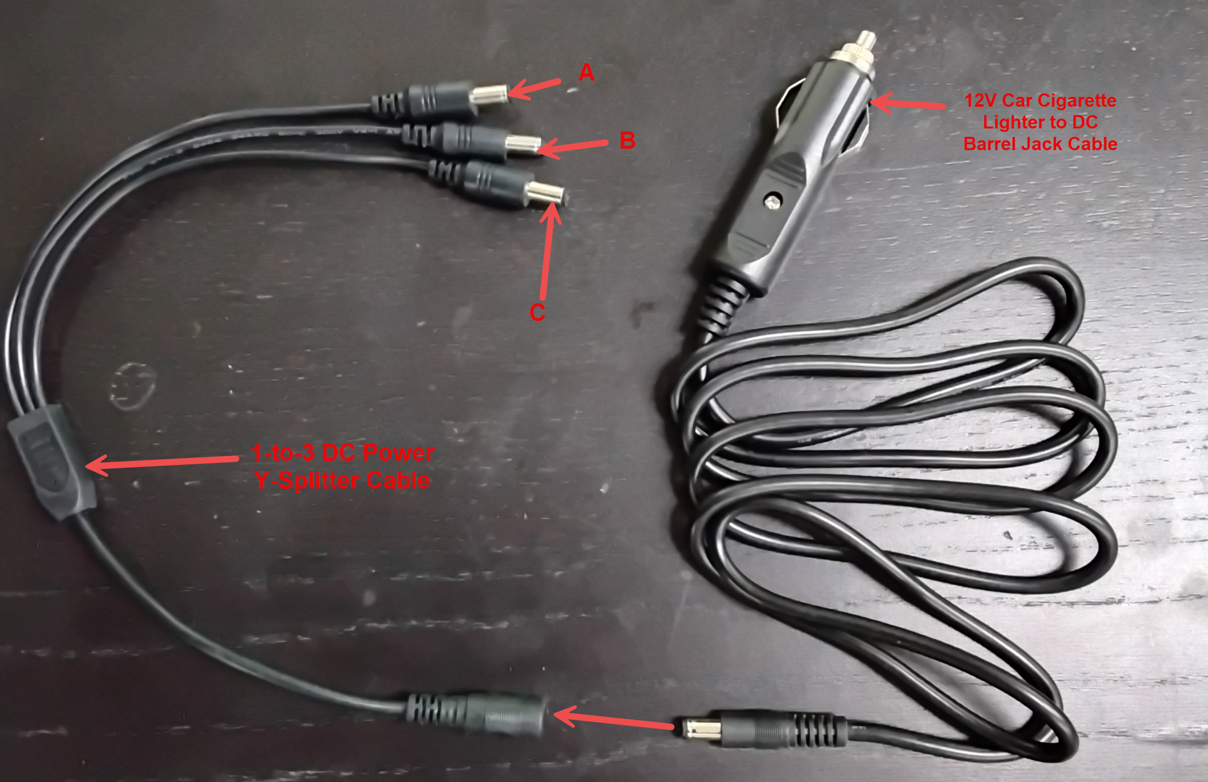
youyourhavehardware setup utilizes the 12V Car Cigarette Lighter to DC Barrel Jack and a 1-to3to-3 DC Y-Splittercables as shown belowSplitter, the connectivityisfollowseasyaandhighlysimple.simplified
| terminal
A Connect terminal B Connect terminal C Connect the 12V Car Cigarette Lighter Jack |
Best Practices and Considerations
-
Provide the specification document: Ensure your installer is provided with the PICOPAK3 PINOUT and CONNECTIONS specification document. This is absolutely crucial for verifying pinouts and maintaining hardware warranty standards during any custom modification.
-
Verify power requirements: Verify the consistent power draw and electrical requirements with your installer. Mobile LPR equipment requires stable power; improper connections or insufficient voltage can lead to unexpected system reboots or data loss during active enforcement patrols.
-
Secure all physical connections: Ensure all cable connections are securely fastened and protected from physical wear or environmental exposure. Routing cables safely and neatly within the vehicle cab prevents accidental disconnection by enforcement officers entering and exiting the vehicle.