
Part 2: Equipment Set-Up
Let'sThe connectMobile allLPR Equipment Setup process outlines the gear.physical connection and configuration of your License Plate Recognition hardware. Its primary purpose is to ensure the Survision camera, PL8RDR computer, and associated peripherals are correctly powered and positioned for accurate plate scanning. This article is intended for OPS-COM administrators and field deployment staff responsible for installing the LPR kit.
Setup and Configuration
This process requires direct physical interaction with the provided hardware components. A typical OPSCOM LPR systemsetup includes a Survision LPR camera, a PL8RDR device,micro-computer (the "brains" of the operation), a 4G/LTE tablet, a Bluetooth printer, and a vehicle mount.
The PL8RDR - (LPR Computer)
This is the brains of the operation and is a small micro-computer that is normally stored in the vehicles truck.
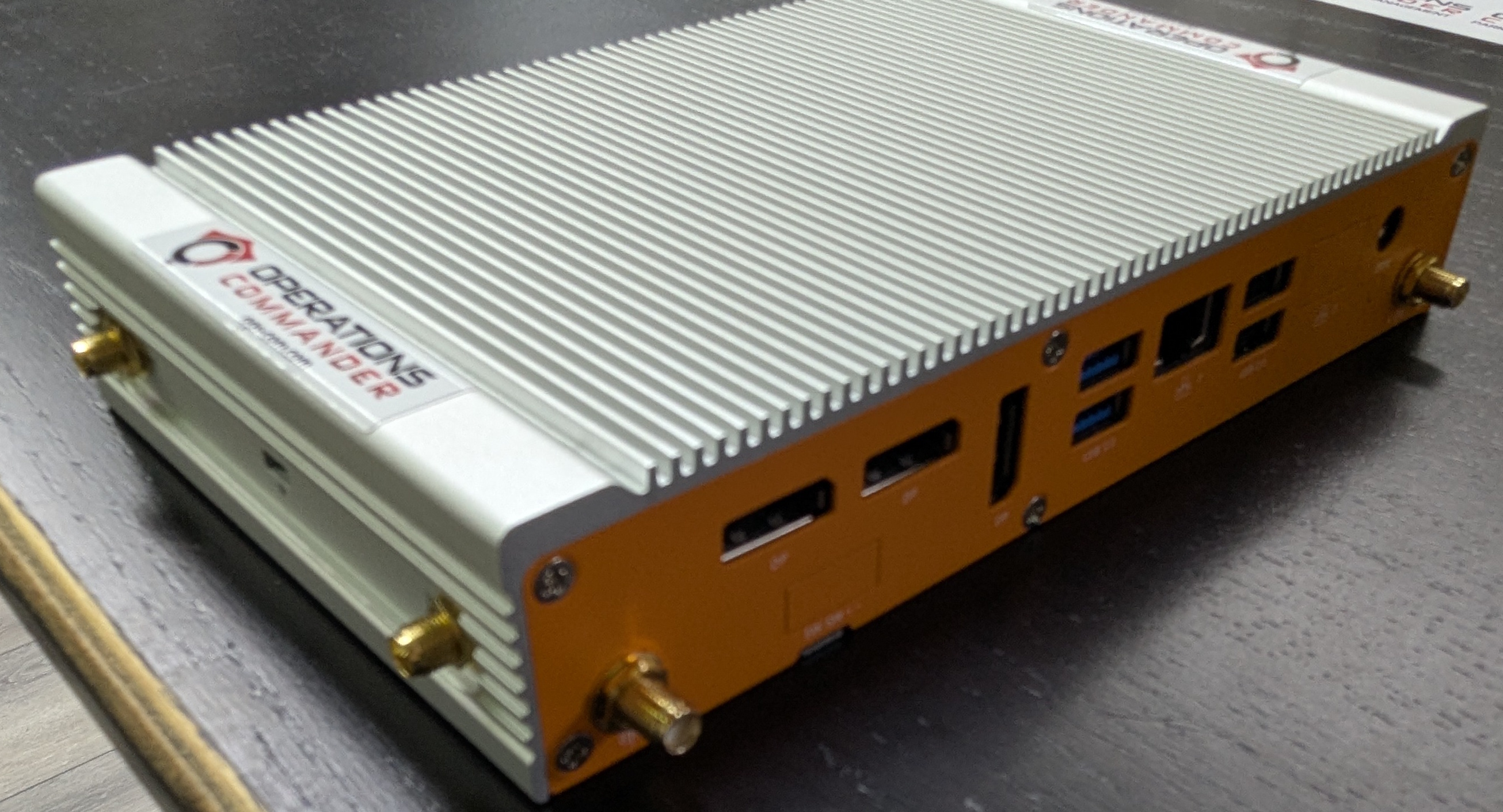
Powering the PL8RDR
There are two options for powering the PL8RDR. PL8RDR: The PL8RDR computer requires a strictly 12V DC power source and must always be connected using an inline fuse to protect the hardware. It can be powered using a vehicle power adapter for field use or a standard wall plug.plug for in-office testing. The setup steps arebelow apply to both power options.
Connecting the same for both options. The PL8RDR uses a 12V DC power source and should be connected with an inline fuse.
Option #1: Using the Vehicle Power Adapter
Equipment
ForInstallers a single Camera setup
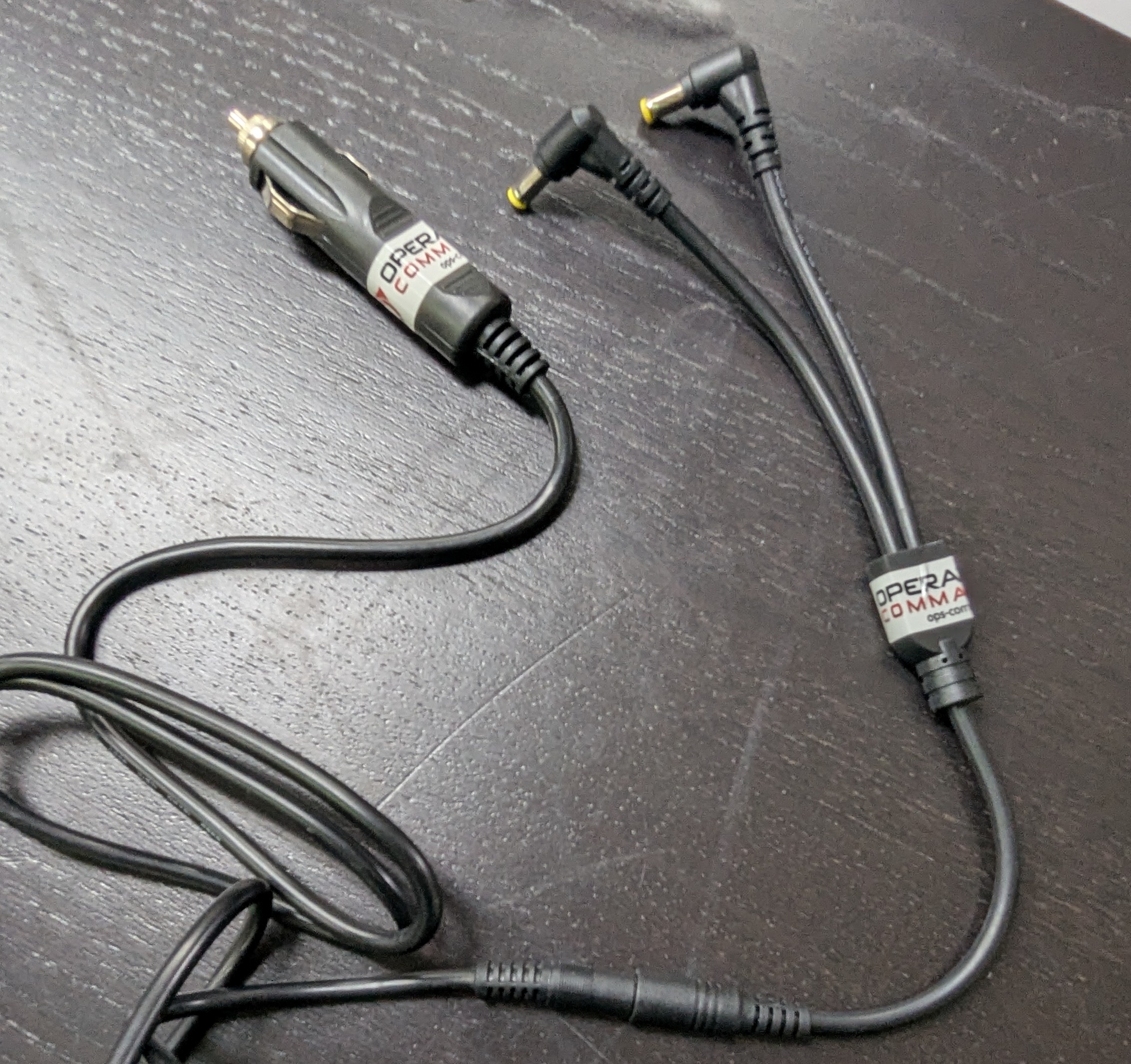
For a 2-Camera setup
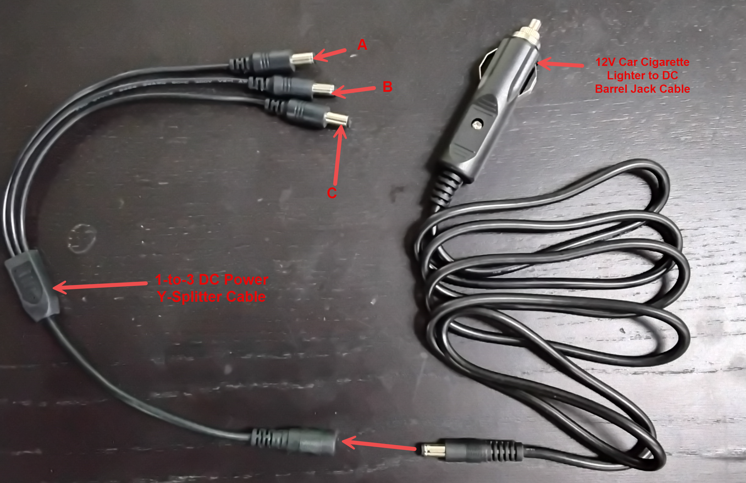
Option #2:Using a wall plug.
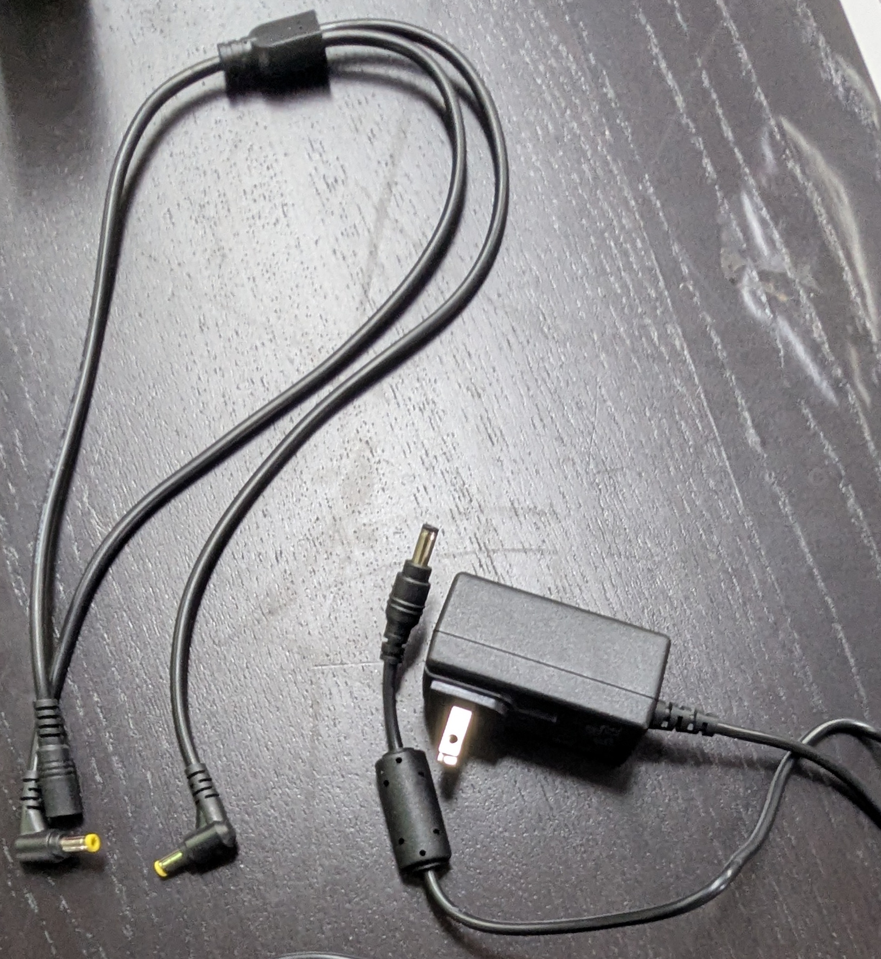
In this guide and pictured below, we are using Option #2: Using a wall plug. If you are setting this up in a vehicle, follow the exact same set-up steps butcan use the vehiclefollowing pluginstructions to accurately route power adapterand instead. The rest ofattach the connectionsrequired remaincommunication antennas to the same.PL8RDR and camera.
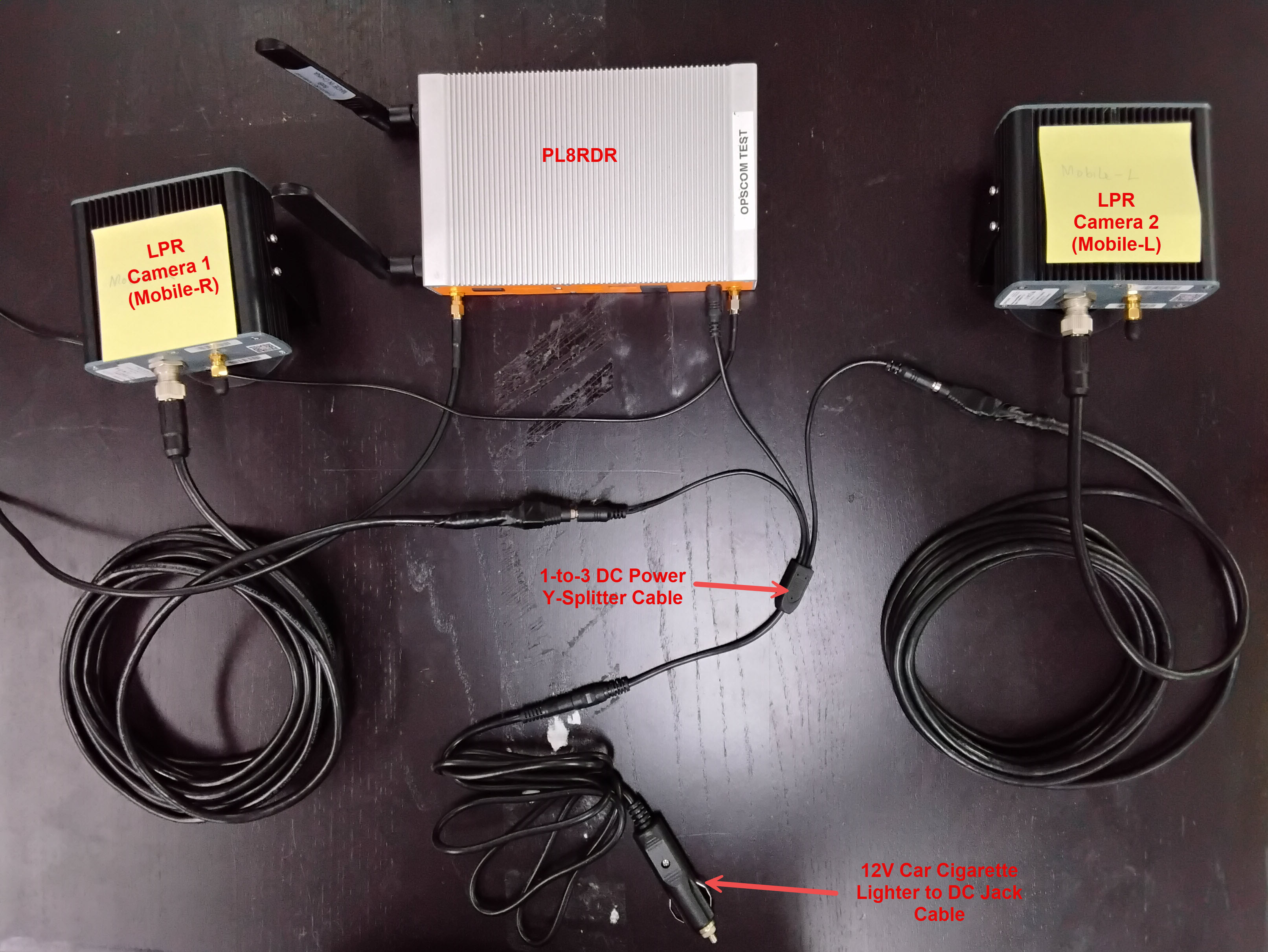
Step-by-Step
Connecting The Wallthe Power Cord
and - Camera
-
Connect the splitter to the
restprimary power cord. -
Plug the opposite end of the power
cord,cordas shown below:
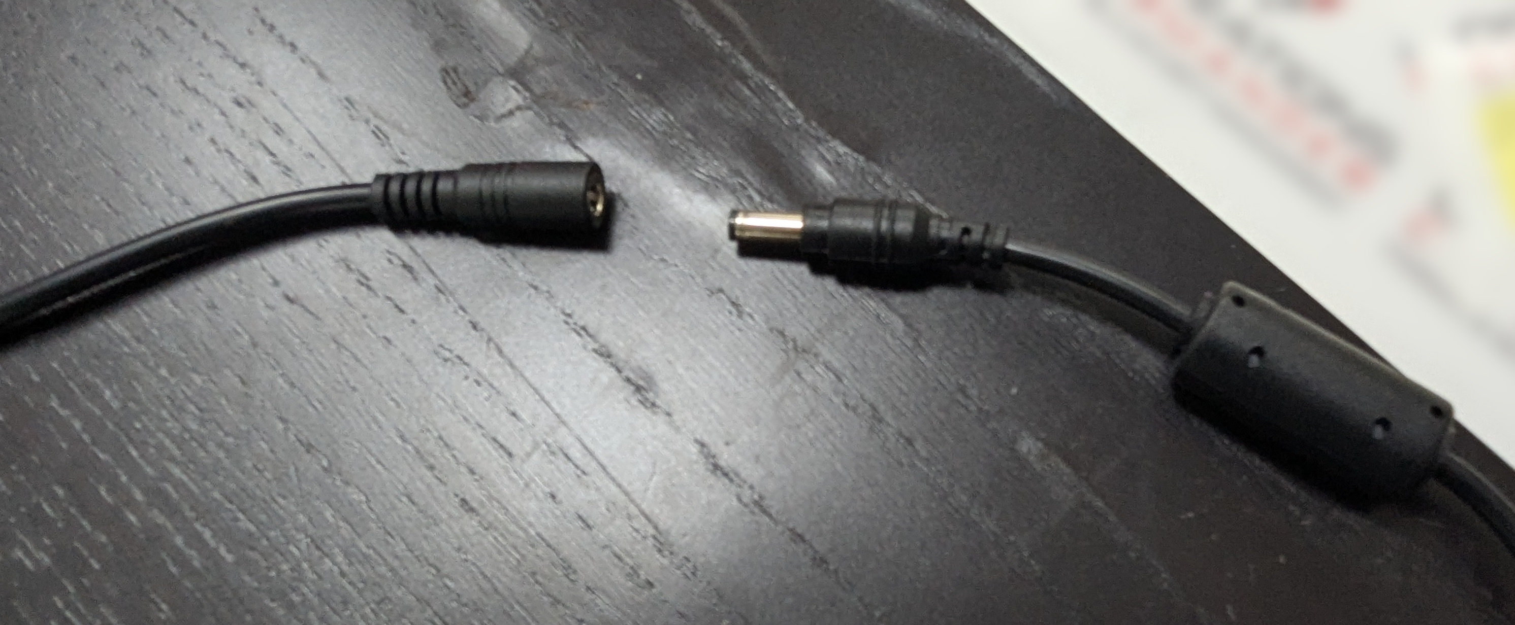
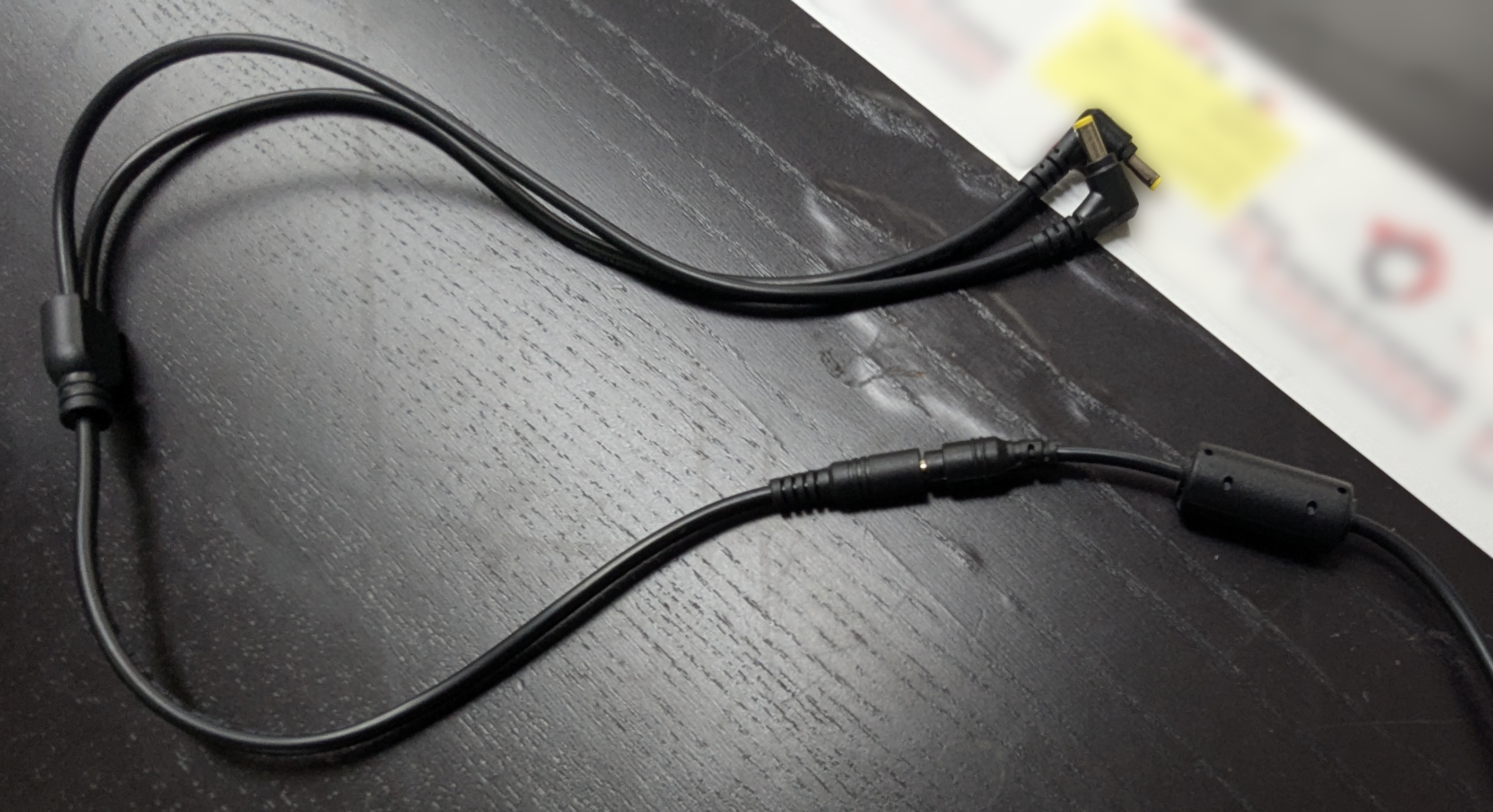
Plug in the other side tointo the wall socket or the vehicle poweradapter, depending on your setup.adapter.Next, get these 3 items ready:LPR power/data cordCameraPL8RDR computer
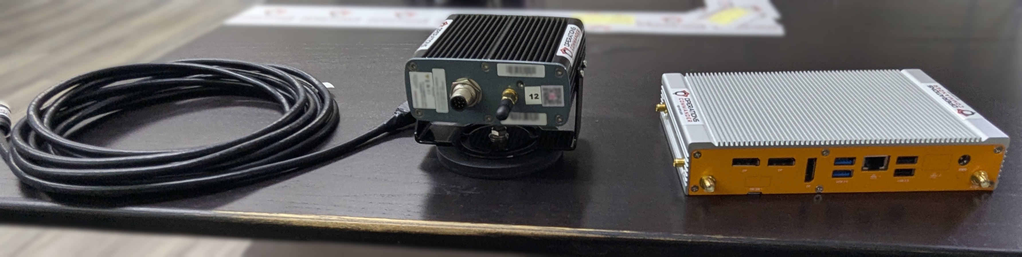
Notice the two different ends on the LPR power/data cord. Pictured below:
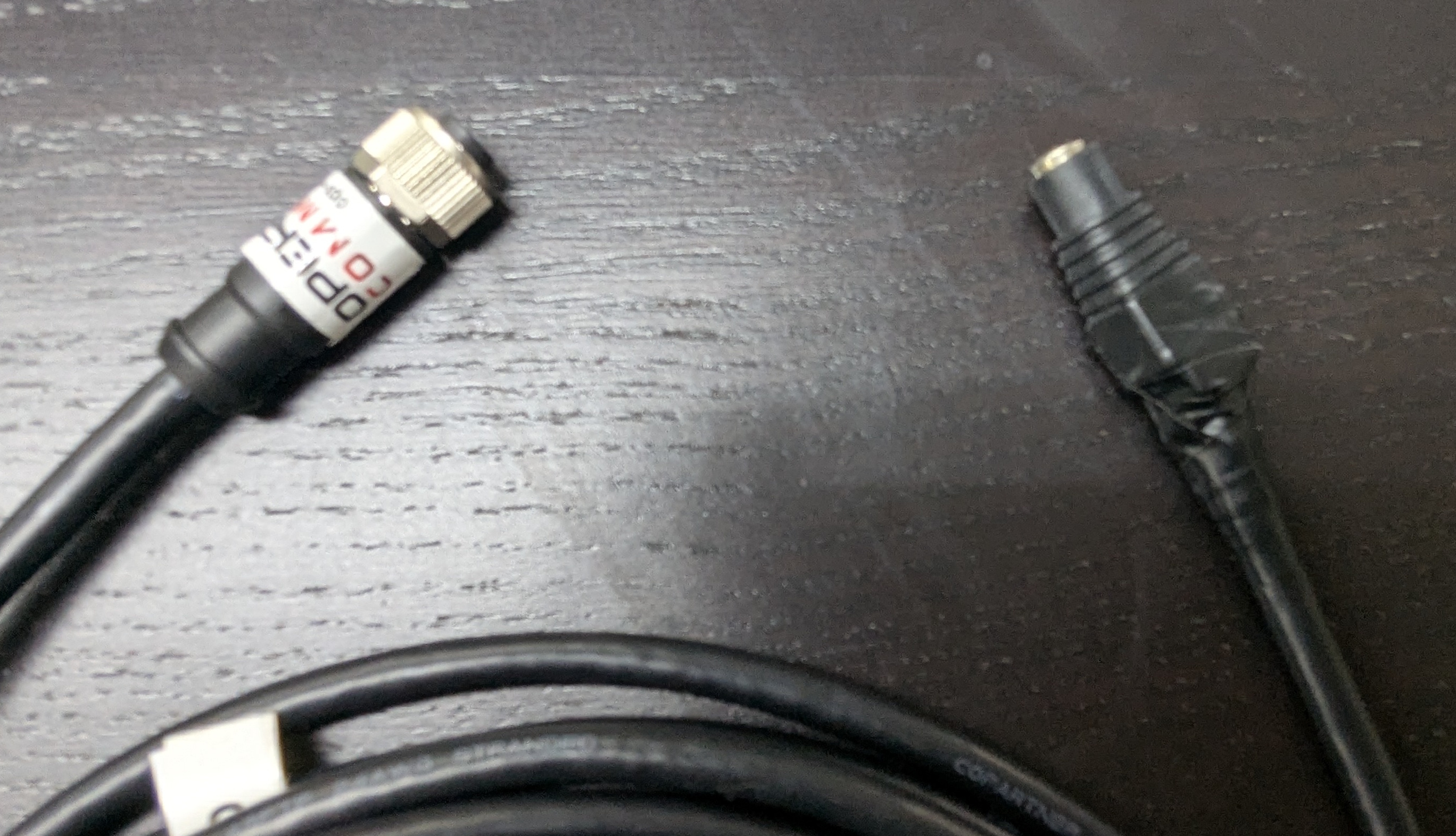
The cable shown above may vary depending on your setup. This version includes a female barrel plug connector.
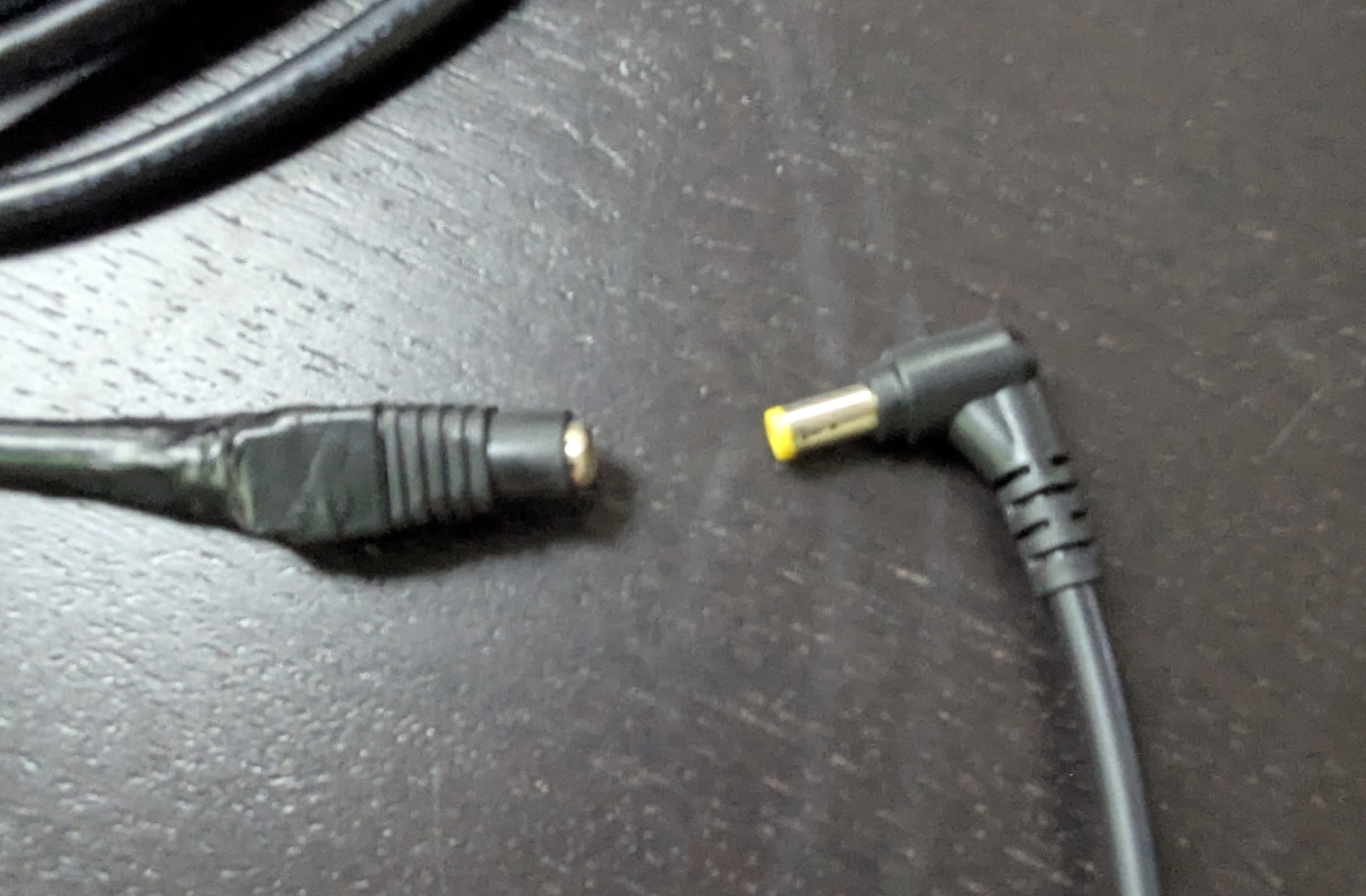
- Connect one of the split power cords to the LPR data/power
cord,cord.as shown below:
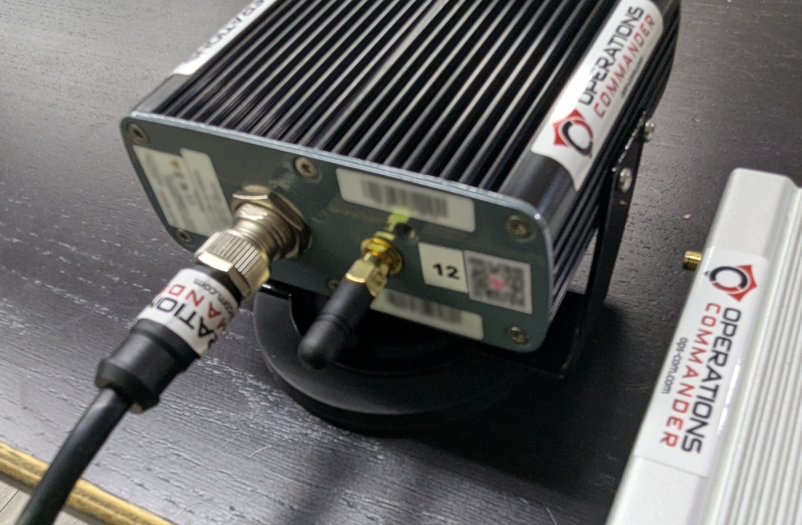
Alignthe pins and attach the cord securely to thecamera,Survisionascamera.shown below:
- Plug
intheotherremaining power source directly into thePL8RDR.PL8RDRYourcomputer.setup should look like the picture below:
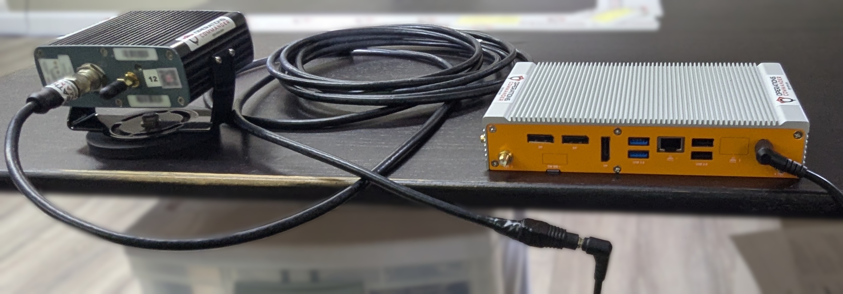
Or the picture below if you have 2 LPR cameras
You will know that youthe haveinitial succeededpower oncesetup youis seesuccessful when the Survision camera emitemits a strongstrong, visible light.
Now you'll need to attach
Installing the Antennas
The system utilizes two LAN antennas and one OPS-COM wireless connection antenna.
-
Attach the corded LAN antennas to the
PL8RDR. This establishes a connection to the OPSCOM servers.All antennas need to be attached as shown or the device will not function as intended.Here are the 3 antennas that you will need, as pictured below:2 x LAN Antennas1 x OPSCOM Wireless Connection Antenna
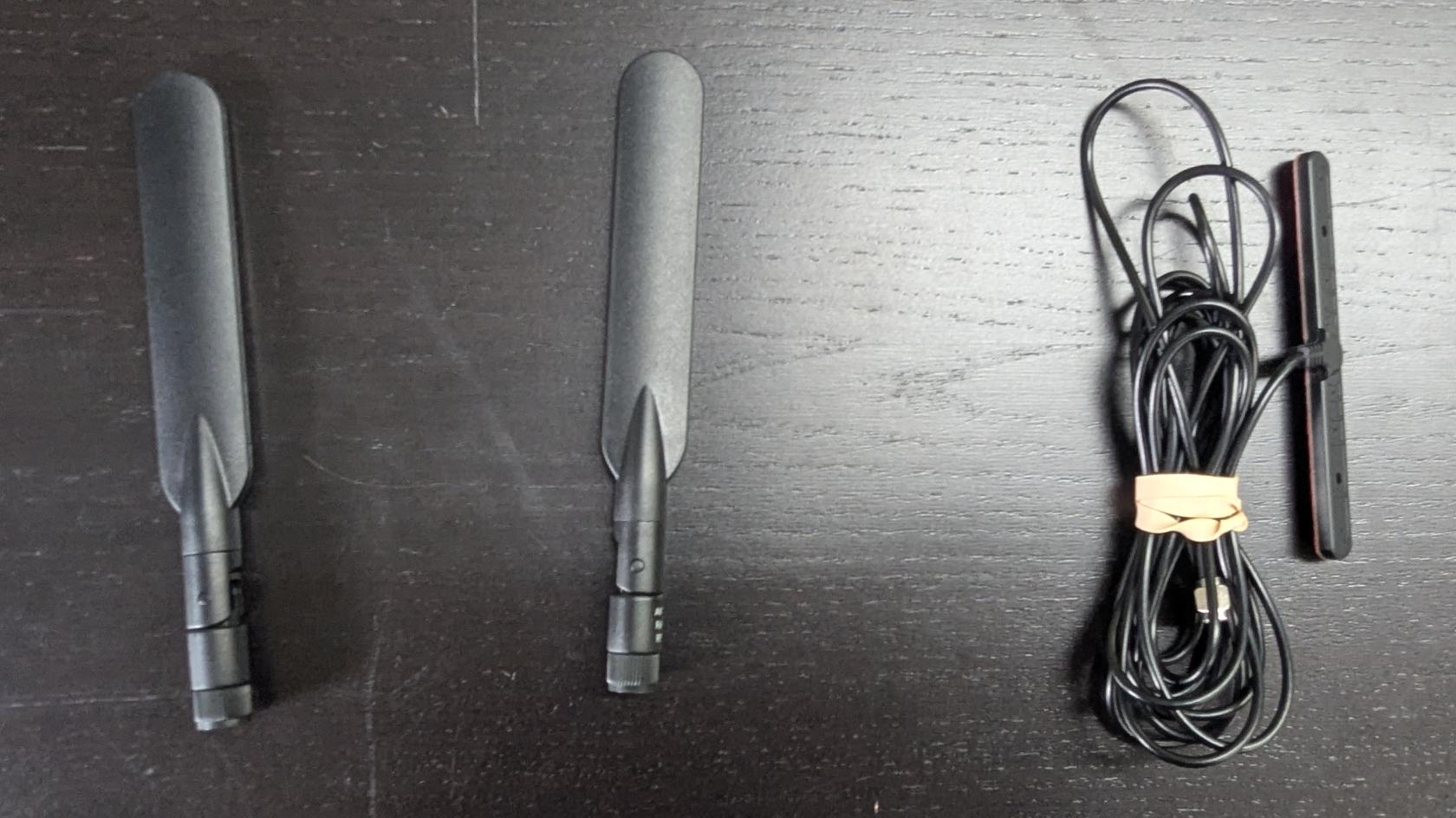
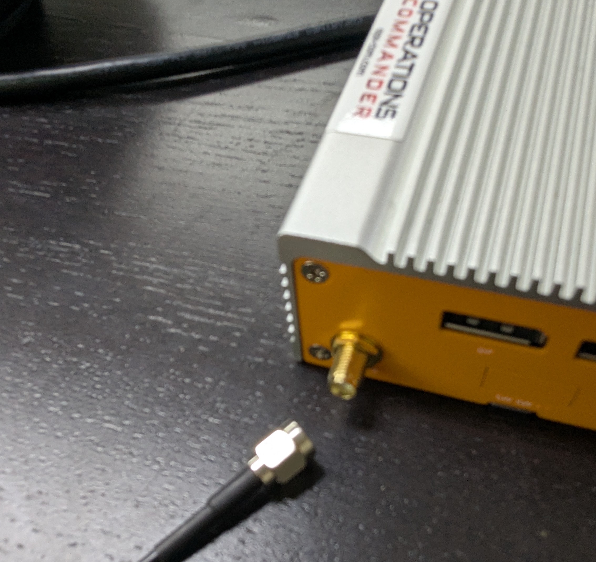
An extra Wireless Connection Antenna (T-Bar) may be included. It may be used if you experience connectivity issues. Otherwise, it isn't required at this time.Attach the cable antennas to thespecific port on the back left of thePL8RDR,PL8RDR.as shown below:
-
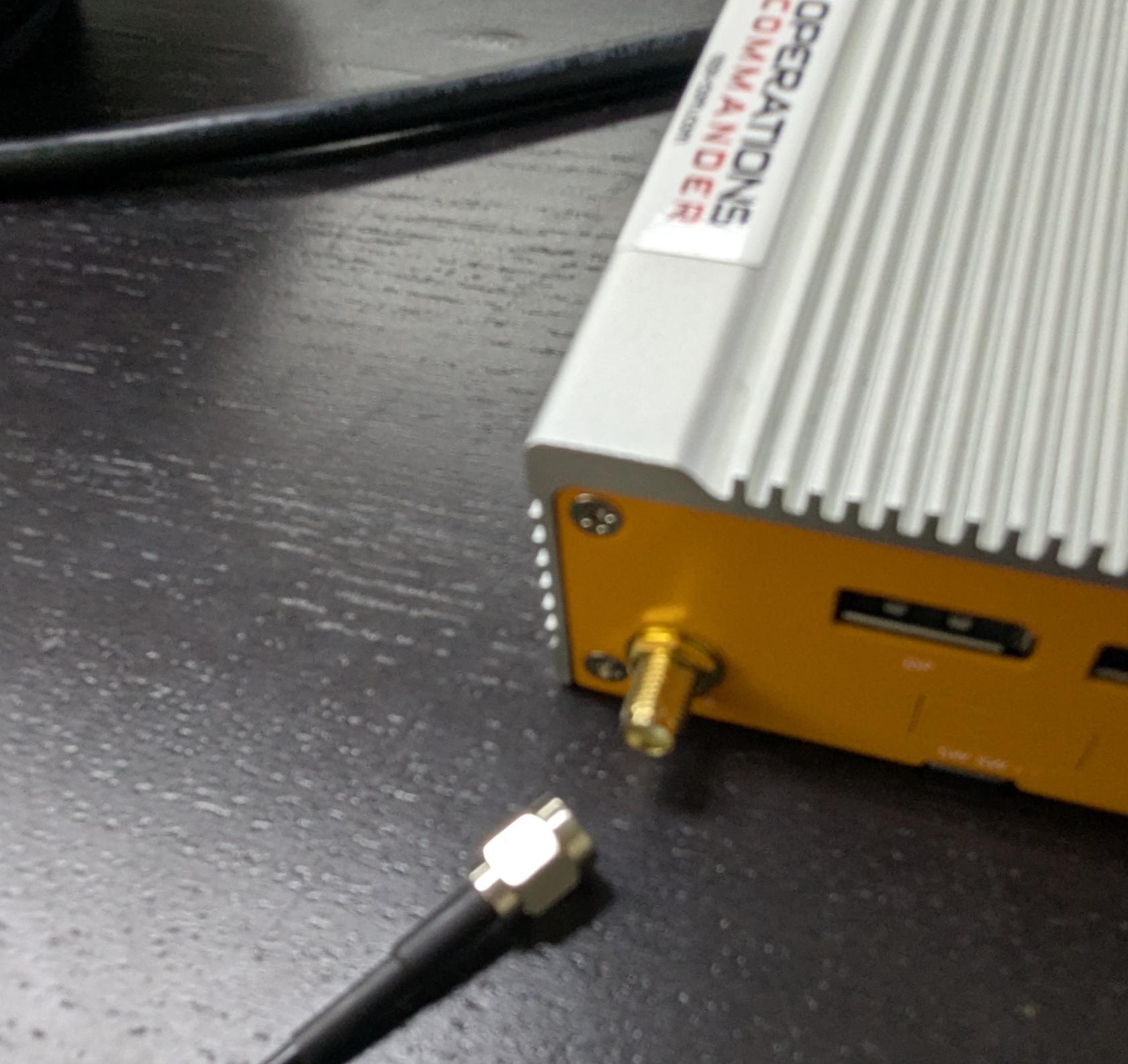
- Lightly screw
inthe side antennas into their designated ports on the side of thePL8RDR,PL8RDRaschassis.shown below.
- Lightly screw
-
Gently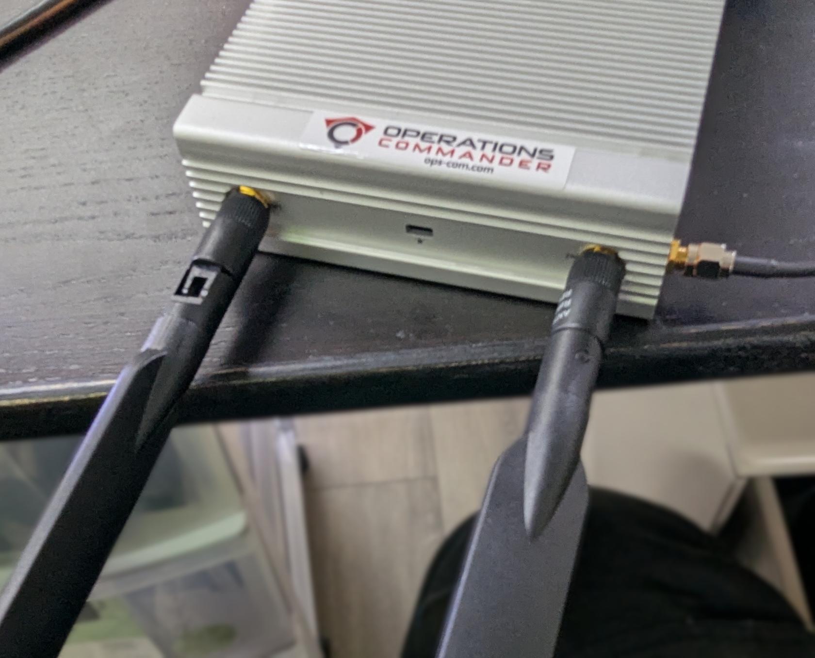
- fold
Makethesuresidethatantennas into an upright position, ensuring the hinge is facing the correct direction.-
Mount or place the corded LAN antennas in an elevated location within the vehicle to ensure a strong data signal.
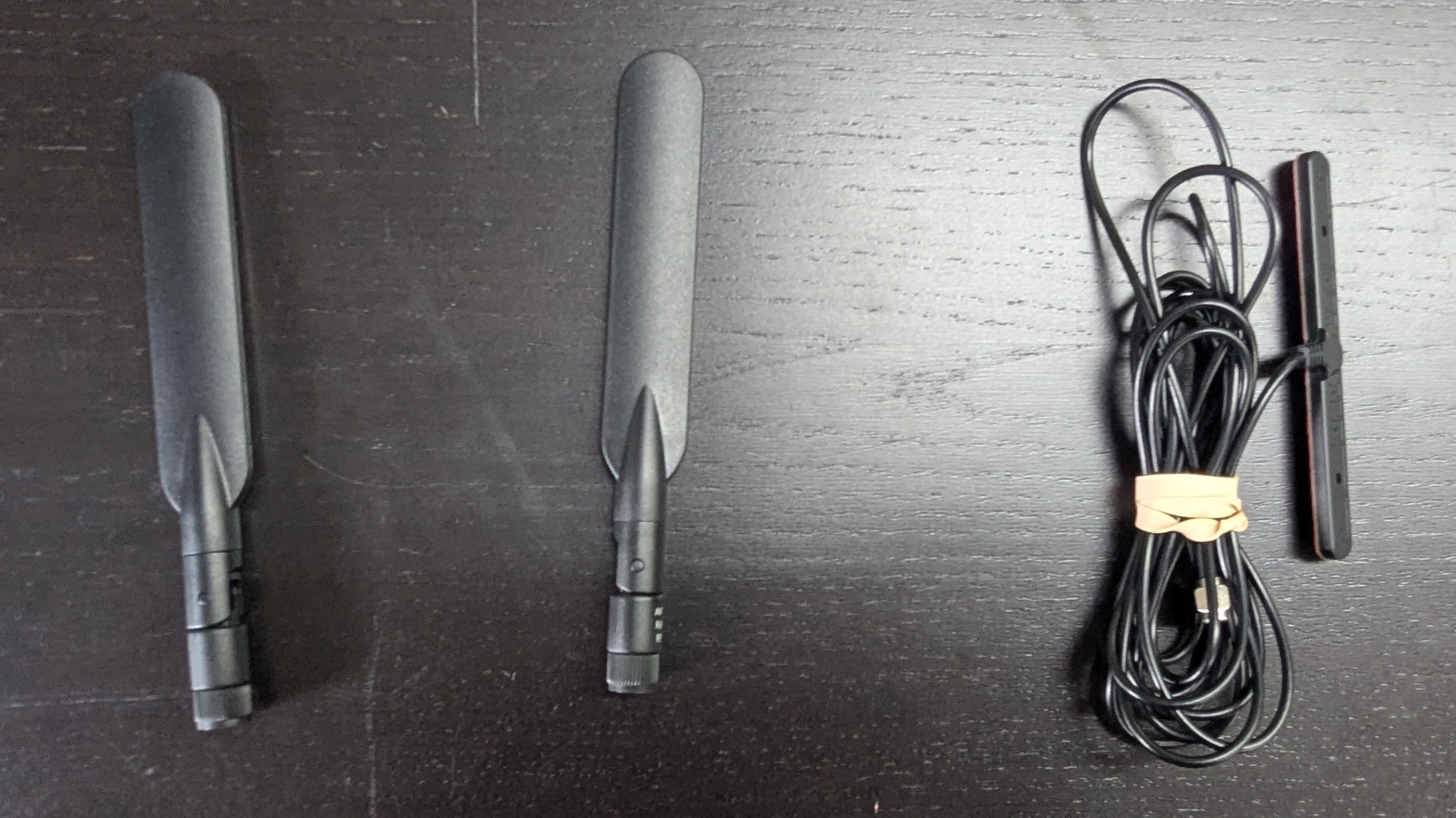
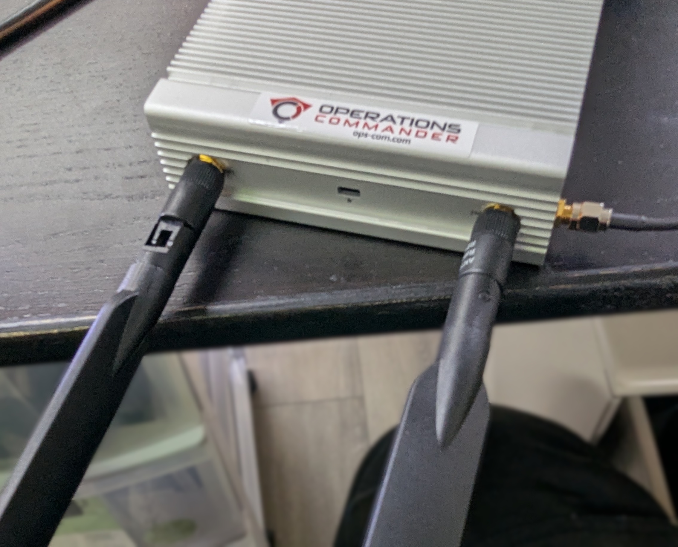
All antennas must be attached correctly and securely. If they are omitted or improperly connected, the device will not establish a connection to the OPS-COM servers and will fail to function as intended.
Positioning the Survision Camera
Proper camera positioning is critical for accurate license plate reads. Installers must physically align the camera and use the software configuration assistant to finalize the setup.
-
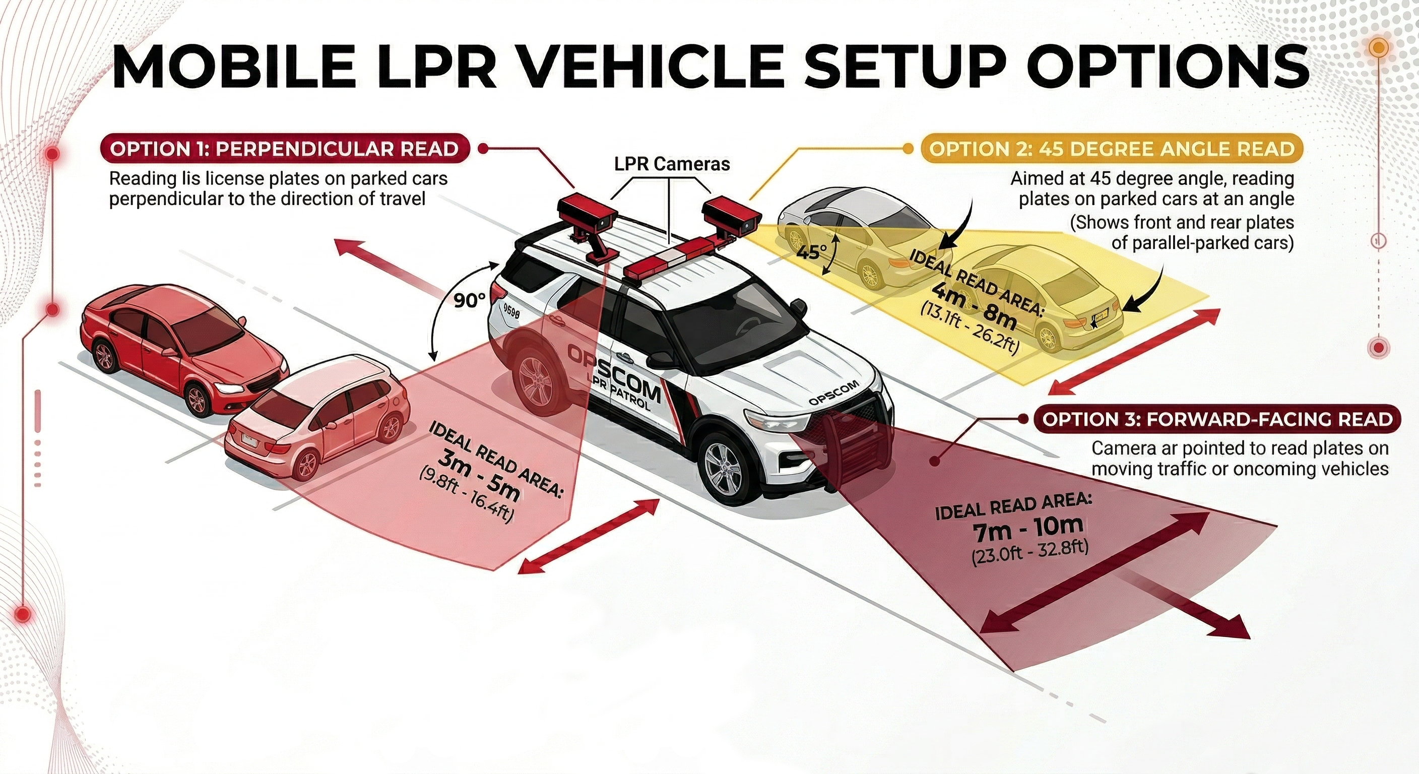
Park your enforcement vehicle behind and to the side of a reference vehicle with a clearly visible license plate (simulating driving past it on the street).
-
Mount the camera on your vehicle so it is physically between 3 and 8 meters away from the reference plate.
-
Angle the camera so it is offset less than 30 degrees from the plates you are scanning.
-
Connect a mobile device or laptop to the pl8rdr.opscom Wi-Fi network.
-
Open a web browser and enter the camera’s IP address to access the management interface.
-
Click Configuration assistant.
-
Click the Next button to navigate through the first three screens.
-
Adjust the physical camera on your vehicle during the fourth screen until the reference plate is perfectly centered in the
correctgreendirection,boxasonshownyourbelow,screen. -
Verify that the lines of text above the camera feed all turn green, indicating the camera is correctly positioned.
-
Click the Next button to proceed.
-
Leave the fields blank on the final screen and
gently foldclick theantennasFinishintobutton.
You may see a system error message after clicking the uprightfinal position.
Best Practices and Considerations
-
Secure the hardware appropriately: Ensure the PL8RDR micro-computer is safely stored in the vehicle's trunk or a secure, well-ventilated compartment.
-
Retain the extra antenna: Keep the extra wireless connection T-Bar antenna on hand. While not required for initial setup, it can be utilized later if you experience persistent connectivity issues in low-signal patrol areas.
-
Optimize antenna placement: Make sure to place the corded antennas in an elevated location with a good data
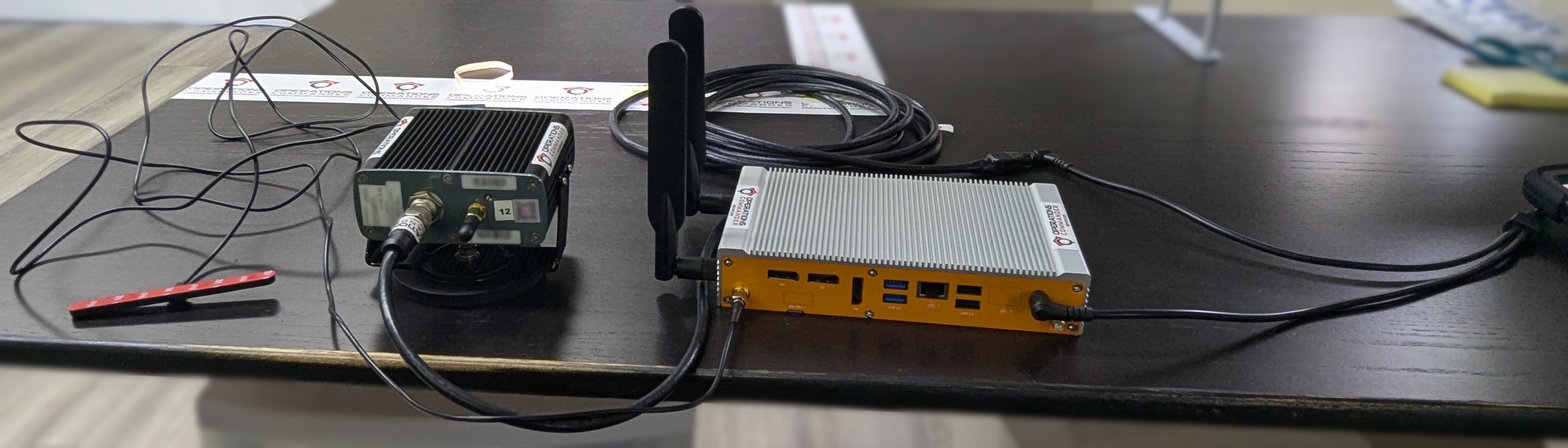
signal to ensure proper connectivity. This is what you should have when you’re done:
Single camera setup
2 Camera setup
Positioning the Survision Camera
Proper camera positioning is critical for accurate license plate reads. Follow these steps to get it just right:
Find Your Reference:signal.ChooseSurroundinga vehicle with a license plate to use as your reference point.Position Your Vehicle:Park your enforcement vehicle behind and to the side of the reference car, as if you were driving past it on the street.Camera Placement:The camera on your vehicle should be between 3 & 8 meters awaymetal from thereferencevehicleplate.bodyItcanshouldinterferealsowithbetransmissionangledif the antennas are buried too deeply in the trunk or cab.-
Maintain strict camera angles: Strictly maintain a camera angle of less than 30 degrees off the
platestargetyouplates.areSteeperscanning.angles will significantly reduce OCR (Optical Character Recognition) read accuracy and result in missed enforcement opportunities.
Use the Configuration Assistant:On a device connected to thepl8rdr.opscomWi-Fi network, open a web browser and enter the camera’s IP address. Click on "Configuration assistant".Set the Camera Angle:Follow the prompts by clicking "Next" through the first three screens. On the fourth screen, you will be asked to set the camera angle. Adjust the camera on your vehicle until the reference plate is centered in the green box on your screen. The lines of text above the camera feed should all turn green when it is correctly positioned.Finish Setup:Click "Next" when you're done. On the final screen, leave the fields blank and click "Finish". You may see an error message, but you can safely ignore it, as the address is configured on the PL8RDR.